- N.B. You may need to adjust the Exposure of your camera when you first add it to your level to match the colors of the Viewport. This is because Unreal uses an auto-exposure and the six cameras of the 360 camera can pick this up differently to the Viewport.
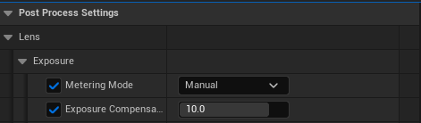
- The 360CameraActor automatically sets an Exposure Compensation of 10 when brought in to a level. This can be too high or low for some scenes. Adjust this setting in the Port Process Settings using the Exposure Compensation slider.
- Exposure is set to Manual by default to avoid seams and artefacts caused by Auto Exposure.
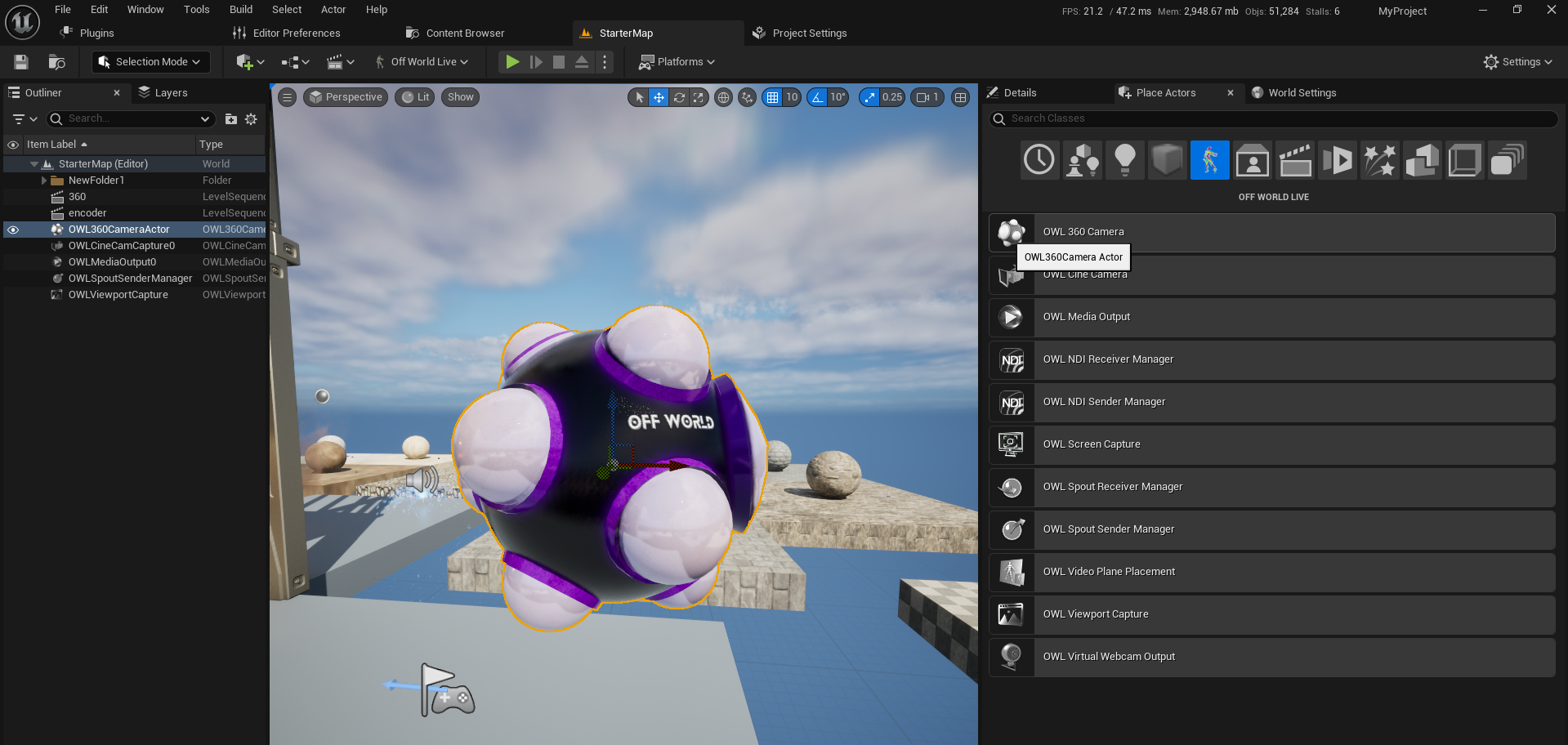
The OWL 360 Camera or Capture component should be used to set up all the details of your content.
- Drag and drop the OWL 360 Camera into your scene:
- If you want to attach an OWL 360 Capture to an existing Cinecam, use a Component:
- Now you can go to the Details panel of the OWL 360 Camera to configure your content:
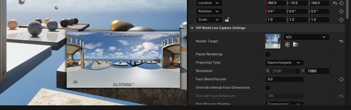
- Render Target: The Render Target is a texture that is drawn every frame. This is useful as a preview and in most cases shows a 1:1 view of what your final render will look like. Use this if you want to preview your content live or if you want to live-stream your content to a headset or projection. When you add a Render Target, the camera preview in Unreal will show your output live in the selected projection:
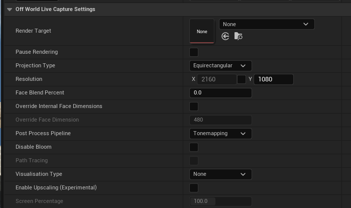
- Pause Rendering: Use this to manage performance when you don't need to preview/ stream your content.
- Projection type: Use this to select the 360/ 180 output you want.
- Resolution: This only sets the resolution of the Render Target, to set your Render resolution, please use the settings in Movie Render Queue.
- Face Blend Percent: Use this to manage seams which can occur with screen space effects like Bloom, Particles, Volumetric fog etc. You should also use this with Stereoscopic 360 to create a seamless render. Recommended setting is 2-5%. You can see more detail here.
- Override Internal Face Dimensions: You can use this to increase the resolution of individual faces to create a higher pixel density.
- Post-Process Pipeline: This should be set to Tonemapping unless you want to use the Seamless 360 Bloom for live-streamed content. If set to Tonemapping then the colors in the Render Target will match the Viewport and the Movie Render Queue.
-
Post Process Update Location: This dropdown controls whether to change any Post Process settings via the Camera Component or the 360 Component. Changes to Post Process Effects via a Post Process volume will still update the 360 camera regardless of this dropdown. When a Post Process setting is ticked in the 360CameraActor’s details panel, then this overrides the Post Process Volume.
- Disable Bloom: This is a tickbox to completely disable bloom in your render, in the case that setting a face blend percent doesn't stop seams.
- Path Tracing: Use this to preview path tracing, it will take some time to create the frame so can't be used in real-time.
- Visualisation Type: If you are outputting Stencil Layers for color grading, you can use this to preview different layers.
- Enable Upscaling: This let's you set a screen percentage for the Render Target output to take advantage of image upscaling using TSR or DLSS. You need to have TSR selected in your anti-aliasing settings or DLSS installed.
- Render Target: The Render Target is a texture that is drawn every frame. This is useful as a preview and in most cases shows a 1:1 view of what your final render will look like. Use this if you want to preview your content live or if you want to live-stream your content to a headset or projection. When you add a Render Target, the camera preview in Unreal will show your output live in the selected projection:
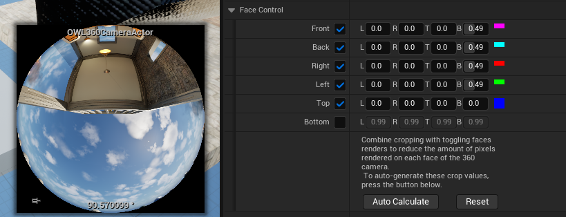
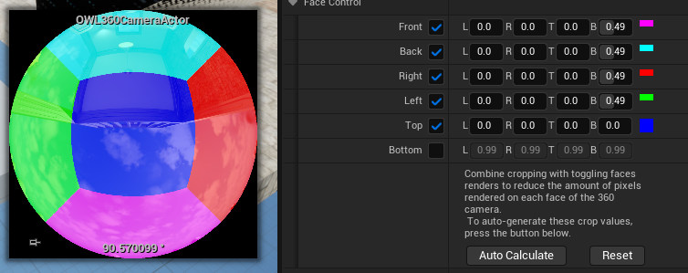
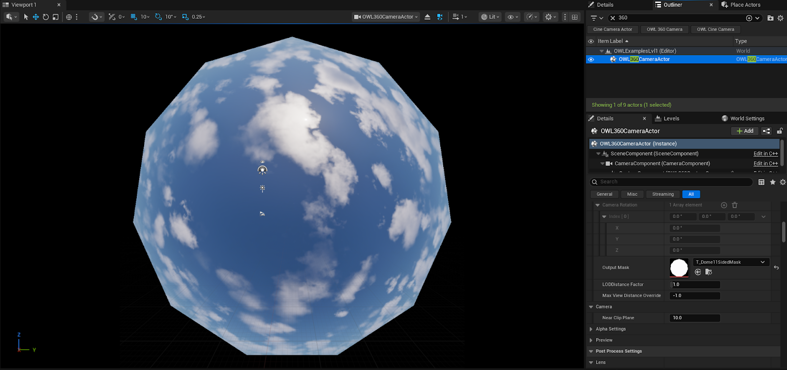
- Face Control: This let's you control which pixels are rendered in your projections. It will automatically update depending on the projection you select above, but you can also manually adjust it if you need. For example see in this Domemaster projection, one face is off and four faces only are rendering half the pixels as only this is required to produce the Dome output. You can use the 'Debug Face Colors' in the Advanced section below to see which faces are being rendered and how:
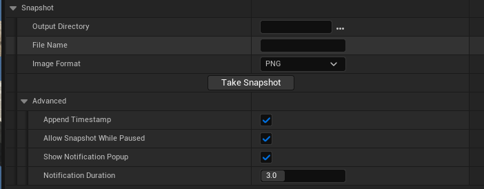
- Snapshot: This let's you output a png direct from the Render Target for preview or sharing with teams/ clients:
- Preview: When ticked, this will show your Render Target output in your Unreal Camera preview window:

- Advanced: This let's you modify the projection, changing your FOV and camera/ cube rotation in case you need to render less than exactly 360 or 180 degrees:
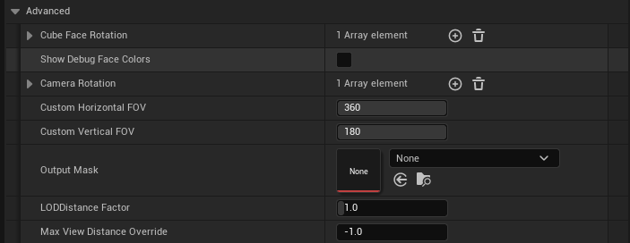
- Changing the Horizontal or Vertical FOV will narrow the range of the projection. This can be used for custom shapes, annular etc
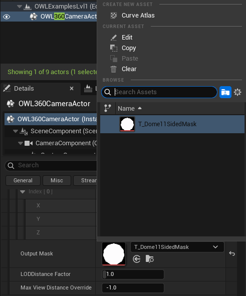
- Output Mask: To add a fully customized crop to the output, use the Output Mask section. Create your custom PNG texture in an image editing software in black and white, with black being the intended masked area. After saving this image locally, drag it into the content browser, then select the Image Texture from the Output Mask section. This will then apply the mask to the output and save disk usage on larger renders. You can then use the Auto Calculate button in the Face Control section to create a crop that matches this mask as closely as possible to avoid rendering pixels that are outside the mask.
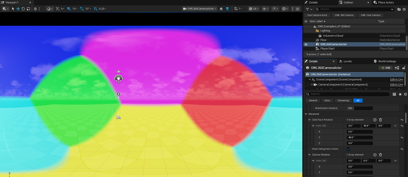
- If you are using less than 360/180 degrees, you may be able to render less than 6 cube faces. To test this you can add the 'Show Debug Face Colors' which will show the cube faces in your Render Target Preview. You can then use the Camera and Cube Face Rotation to rotate the view to only use the cube faces that you need. See more information here.
-
Use Cube Face rotation to orient the seam points of a render in a place that will reduce the visibility of seams in a render. This example shows placing the seams on the horizon line which can be effective in reducing seams in driving plates. The show Debug Face Colors is useful for making the cube faces visible when orientating them.
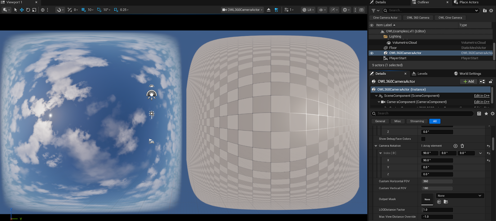
- Setting a Camera Rotation value can enable you to rotate the 360 output of your image while leaving the actual camera transform unchanged. This can be helpful for creating keyframed animations, then editing your output at a later stage for a specific output format.
- Camera: Near Clip Plane value can be increased if you automatically want to not render objects that are too close to the 360 Camera:

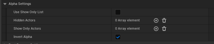
- Alpha Settings: You can use these to create an alpha output as explained here:
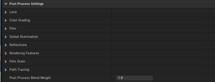
- Post Processing Settings: When the Post Process Update Location is set to 360 Component (see setting above), these Post Process Settings will be editable and will carry through to the final 360 render. Most Post Process settings will not cause a problem for 360 renders, but Bloom, Dirt Masks and other screen space based effects may need a significant Face Blend Percentage to work as intended.
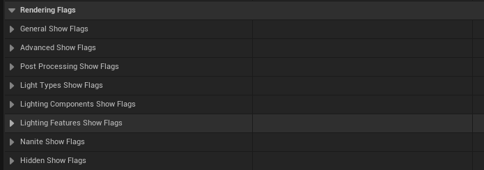
- Rendering Flags: You can toggle these on/ off to preview the effect of different render passes in the Render Target
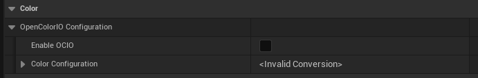
- Color: Use the Color section to add OCIO color configurations to the Render Target Preview only. Load a config in to the content browser then set this asset as the Configuration Source, then choose the Transform Source and Destination from the OCIO config file as explained here.
- Blueprints:
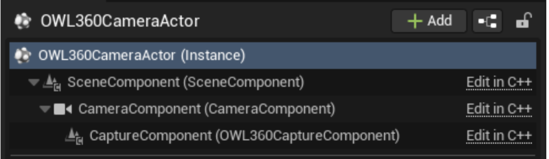
- The OWL 360 Camera Actor is made up of a Scene Component, a Camera Component and a Capture component. The details for all of these components can be accessed from the OWL360CameraActor, but to change some of these settings via Blueprints you will need to know which settings are a part of which component.
- The Transform Settings for the Camera are controlled just as any other Actor in Unreal Engine and can be keyframed or controlled dynamically via Blueprints.
- The Off World Live Capture Settings are unique to the Capture component and can be controlled via Blueprints by accessing the CaptureComponent as a child of the 360CameraActor, below is an example of setting some of the settings Dynamically via a Custom Event in the Level Blueprint:

