OWL 360 Degree Camera and Component
A 180 and 360 Degree Stereoscopic Camera and Component for Unreal Engine with precise Viewport color matching, output to a Render Target, Alpha Channel support, Movie Render Queue integration and various other features.
Last updated 28 days ago
Overview
The OWL 360 Degree Camera and Capture Component let you capture 180 and 360 Degree live outputs from Unreal with identical colors to your Viewport and a wide range of additional useful rendering a compositing features.
You can use it for three main purposes:
Live-streaming 180/ 360 content from Unreal Engine over-the-network or to the internet via a wide range of media protocols.
Creating
Sequenceswhich can be rendered inMovie Render Queuevia our180/ 360 Renderingpass.Previsualising your renders live (to check proportions, pacing etc), before you send them to
Movie Render Queue, via VR Headset or a Digital Twin of your venue, which can even be done for a full show.
360 Degree Camera Actor
The OWL 360 Degree Camera is a standalone Actor that you use in your Unreal level like any other camera.
To use the OWL 360 Degree Camera:
Go to
Place Actorsand in the Off World Live section find theOWL 360 Camera Actorand drag and drop it into your levelYou can now use the
Camera Actorin Unreal like you would any standard camera:
360 Degree Capture Component
The OWL 360 Degree Capture Component adds the OWL 180/ 360 Degree capture capabilities to whatever Camera or Actor you attach it to. This is useful if you have an existing sequence which you want to add a 360 Camera output to.
To use the OWL Capture Component:
Select any Unreal
Camera,CinecamorActorin yourWorld Outlinerand at the top of itsDetailspanel clickAddand type and selectOWL 360 Capture: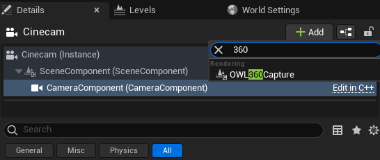
This will add an
OWL Capture Componentto yourCamera/ Actorwhich you will see in yourComponentslist. Make sure that thisOWL Componentis attached to yourCinecamorActorby dragging it and seeing the green tick: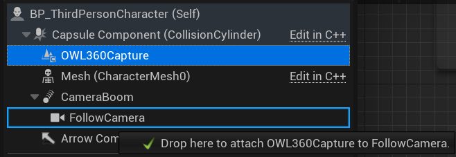
Use with Movie Render Queue
The
OWL 360 Render pass for Movie Render Queuewill automatically sync with whatever360 Camerais selected in theCamera Cutsof your UnrealSequence.You can use either the
360 Camera ActororCapture Component.Whatever settings you select below, will automatically be picked up in
Movie Render Queueapart from theResolutionsetting, which you independently set inMovie Render Queue.
Previsualisation
The
OWL 360 Camera/ Componentis excellent for pre-visualisation because it color-matches yourMovie Render Queueoutput, while also rendering in real-time.So instead of waiting for hours/ days to see what your render will look like, you can preview it in real-time on a screen or headset to get your shots perfectly as you want them before initiating your final pixel high-resolution output.
This is particularly useful for thinking about audience details like the proximity of objects to the camera, scale of your scene to the viewer and the pace of the camera through your levels.
Set-Up
You can live-stream the
Render Targetof the camera through ourSpout/ NDI Sendersto either a headset or venue previsualisation software.If you are outputting VR content then you can use the VR.NDIUntethered app in Oculus or the VXIO app for Apple Vision Pro to receive a live NDI feed direct to the headset (with
stereoscopicsupport).With DLSS enabled, it should be possible to have
4Kresolution live output at20-30FPSwhich is very effective for previs.
If you are making content for a Dome/ immersive venue, you can use the
DomeViewer softwareboth in Oculus or Windows to preview your content in a digital twin of your venue (either birds-eye or as an audience member):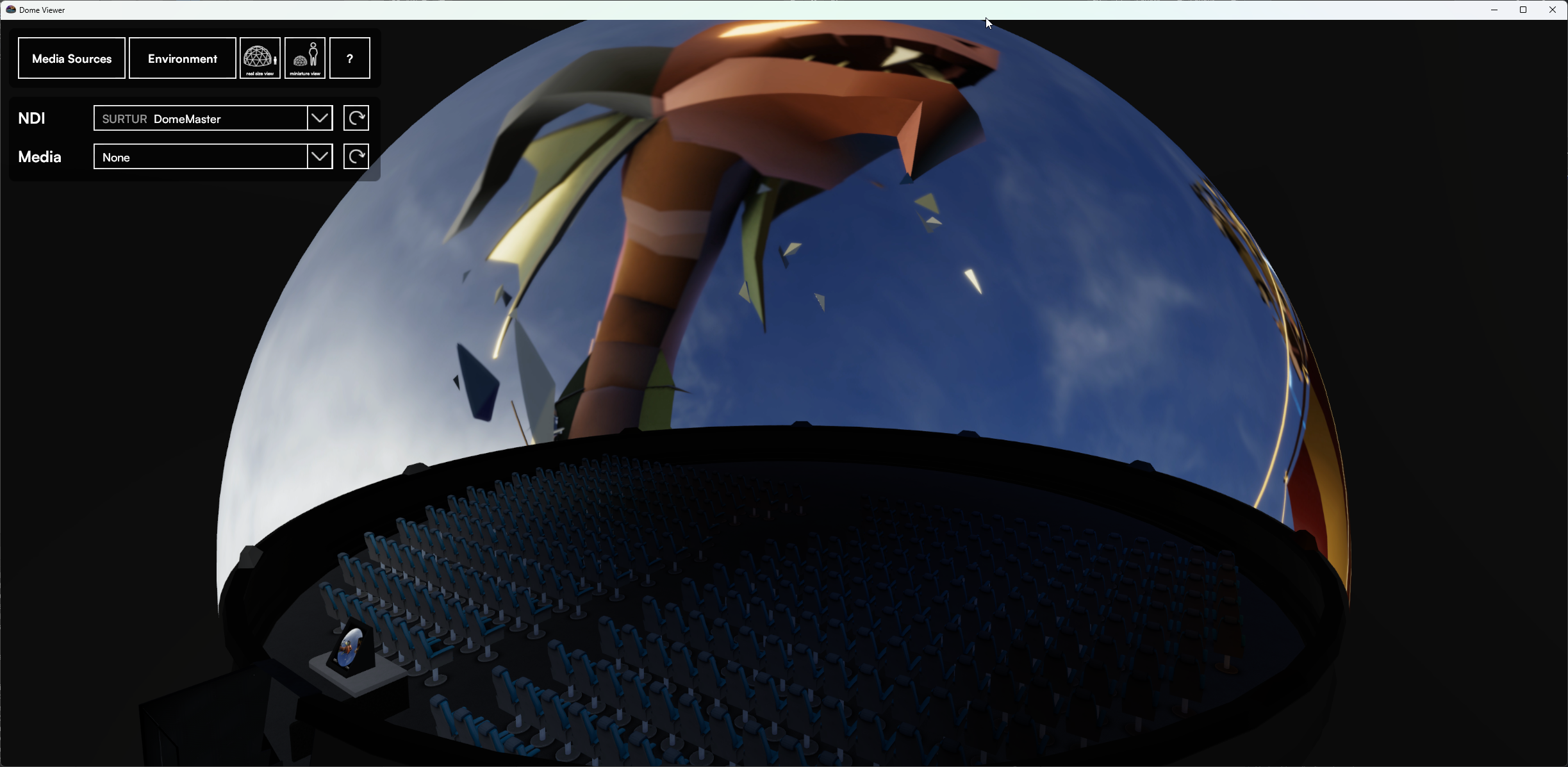
You can also build a digital twin of your venue in Unreal and use the
Media Input Wizardto set up anUnreal Media Platewith the correctMeshof your venue’s screen.You can then stream the
360 Camera/ Componentoutput into your digital twin via theOWL Spout/ NDI Sendersand it will play with perfect color accuracy in your virtual venue.
Live-Streaming
You can live-stream the Render Target of the OWL 360 Camera/ Component using both the OWL Media Outputs and Unreal’s Media Capture framework:
OWL Media Outputs
The easiest way to set this up is to use the
OWL Media Output Wizard, which will let you set up anOWL 360 Cameraalong with any media outputs you need.OWL has outputs for Spout, Virtual Webcam, RTMP, SRT, RTSP, HTTP and Save to File which aren’t available in Unreal.
Alternatively, you can select the
Render Targetfrom the360 Camera/ Componentin any of the OWLMedia Output Actorsto instantly live-stream, as explained in their individual documentation.This works in Editor, Runtime and in Packaged games.
Unreal Media Capture
Unreal has a Media Capture Framework which can send
Render Targets.It has a large number of configurations and is excellent for studio outputs such as capture cards and SMPTE 2110 (Rivermax), which you will need to configure by adding their respective plugins and media captures.
You can also use the OWL Spout and NDI Media Output integrations via this method, to take advantage of the studio workflow configuration options.
It is for Editor/ Runtime usage only so won’t work in packaged games.
To set up:
Go to
Edit> Pluginsand ensure that theMedia Framework UtilitiesPlugin is enabled: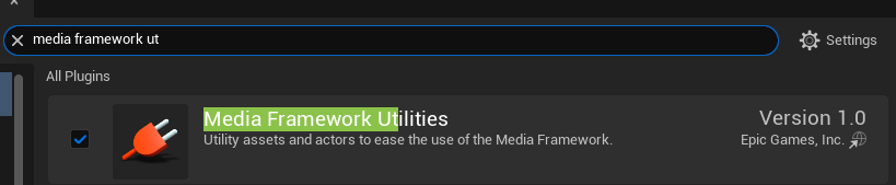
In
Windows> Virtual ProductionselectMedia Capture: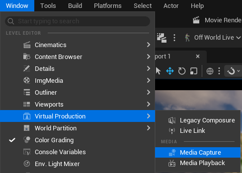
In the
Media Capturewindow, select theRender Targetyou want to send from the list and select theMedia Outputyou want to send it via and then pressCaptureto begin sending: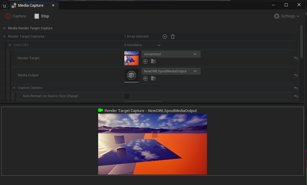
Blueprint Set-Up
The
OWL 360 Camera Actoris made up of aScene Component, aCamera Componentand aCapture Component: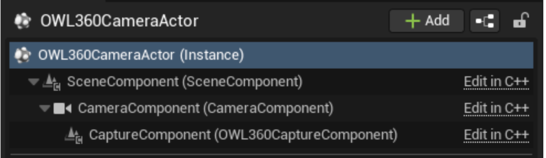
The details for all of these components can be accessed from the
OWL360CameraActor, but to change some of these settings via Blueprints you will need to know which settings are a part of which component.The
Transformsettings for the Camera are controlled just as any otherActorin Unreal and can be keyframed or controlled dynamically via Blueprints.The Off World Live
Capturesettings are unique to theCapture Componentand can be controlled via Blueprints by accessing theCaptureComponentas a child of the360CameraActor, below is an example of setting some of the settings dynamically via aCustom Eventin theLevel Blueprint: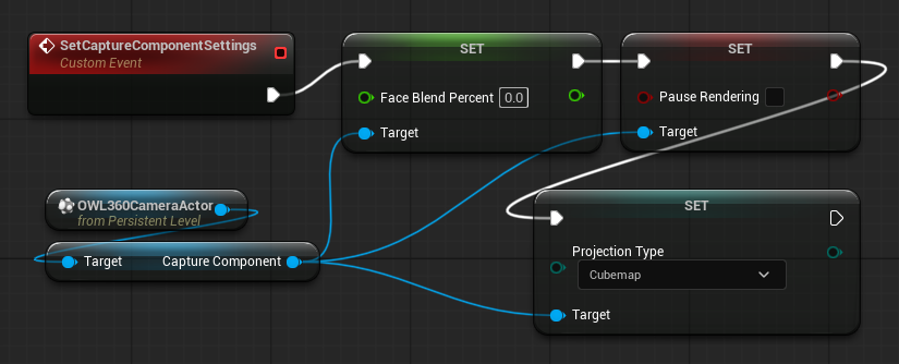
Performance
Exposure
You may need to adjust the
Exposureof your camera when you first add it to your level to match the colors of theViewport.By default, the
360 Camera/ Component,is set toManual Exposurewith anExposure Compensationof10:
This may not match the
Auto-Exposureof Unreal, so you should adjust the value in theDetailspanel until your colors match.For more information see the
Exposuresection inTrouble-Shootingbelow.
Seams
The
OWL 360 Camerauses a cubemap of cameras to generate its raw pixels.Each of these cameras runs Unreal’s post-process effects separately and so there can be issues with
screen-spaceeffects, which use the edge of the camera (since the edges of the separate cameras will be different).It is mostly quite easy to manage such issues using the
Face Blend Percentoption which overscans each of the cameras and blends the edges imperceptibly to remove any clashing pixels (see the vertical line below disappear for example):
There can also be issues with particle based effects like
Niagarabut these are easily managed by changing the settings of the particle system.You can see more information how to manage these issues in the
Trouble-Shootingsection below.
Frame Rate
Rendering to the Render Target is performance intensive because you are rendering an additional set of pixels to your Viewport and your output is likely much higher resolution than your Viewport.
To increase your live frame rate from the 360 Camera/ Component the main options are:
If you are just using the camera for previz, then you can set a very low resolution, which will be enough to see the
Editorpreview and see the effect of post-process changes etc.You can use the
EditorandRuntime Viewport Renderingtickboxes in the OWL Editor drop down to switch off theViewport(If you haveNanitein your scene, you cannot switch off the EditorViewportor it will crash Unreal.)
This is a toggle that you can also activate in Blueprints.
Enable upsampling with
TSR/DLSS, with the setting in theDetailspanel of the360 Camera/ Componentfollowing the guide below. This is particularly effective at higher resolutions.
Visual Quality
N.B. Check the Exposure Compensation section above if your 360 Camera is darker or brighter than your Viewport to easily align the two.Bloom is set to 0 by default in the Details panel of the 360 Camera/ Component because it can cause seams but you can use the tips below to manage it.
The
OWL 360 Camerauses the identical rendering pipeline as the UnrealViewportand so should have complete color consistency with what you see and do in theViewport.This includes responding to
Post Process Volumesbut certain post-process effects can cause visual issues as mentioned in theSeamssection above with tips in theTrouble-Shootingsection below.You can use
OCIOto deliver a precise color pipeline if you need it for your production purposes.In this respect the
OWL Cinecamis more color precise than Unreal’sPanoramic Capture Componentwhich uses aScene Capture 2D Actor(not the same as theViewportrendering pipeline) with variousScene View Extensionsto add post process effects.If you use
DLSSthen you may see a reduction in visual quality, especially in very fast moving scenes because of the predictive nature of the upsampling algorithms.
Lumen vs. Path-Tracing
The
OWL 360 Degree Camerasupports bothLumenandPath-Tracingrender pipelines.Lumenis the defaultGlobal Illuminationmethod for Unreal Engine and is highly recommended.It renders significantly faster (>10x/ frame) than
Path-Tracingand can be combined withUpsamplingto increase this even further.Path-Tracingdoesn’t offer any advantages over other CPU-based renderers like Arnold, V-Ray or Corona, but can be useful in very specific circumstances such as with Unreal’sMetahumansor to better understand the behaviour of light in your scene.Lumencan cause seams to appear (differences in visuals at the edge of the six faces that generate the camera image) but these are easily dealt with following the tips below.
Projection Types
Cubemap
This is the default
projection typefor generating the pixels for amonoscopic 360output.If your VR media player supports it, then it’s recommended because it has around
30%lower file size thanequirectangularand therefore can use a lowerbitrateto achieve the same quality, making it more performant.It is also a useful format for rendering content which you want to convert to esoteric projection types in post-production software.

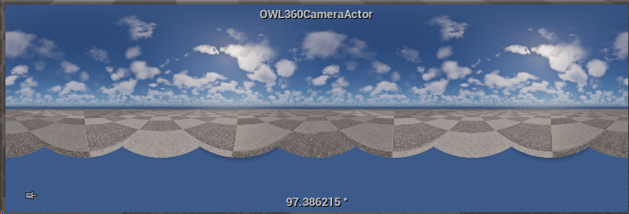
Equirectangular
This is the most common
projection typeused formonoscopic 360video and it can be used for streaming or playback on all360content systems.It is the default projection used in post production software because it offers a continous image and therefore is easy to do color grading and compositing with.
You can customise the
Vertical and Horizontal FOV,as explained below, if your final output doesn’t require the full sphere of pixels.
180 Equirectangular
This is an
Equirectangularwith a180 degreeField-of-View.It’s sometimes used in non-conventional dome venues, like the Sphere Las Vegas, because you can use the
Advanced FOVsettings plus amaskto contrain the pixels to the exact dimension of your curved screen.
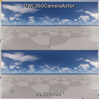
Stereo 360 Equirectangular
This is the default projection for
stereo 360content for VR headsets.It requires a very large resolution and so generally
stereo 180 VRis recommended for a better viewer experience.The two eyes are rendered in a top-bottom format, one equirectangular projection for each eye.
The
Stereo Eye Separationsets the Interocular Distance (between the eyes) with a default value of6.5(in default Unreal world units = 6.5cm).N.B. Our projection offers correct stereo output for the full x-axis 360 degree viewing perspective (including sides and behind the viewer) but it may have seams where it connects with the top and bottom faces (see VR guide for how to manage these).
Stereo VR180 Equirectangular
This is the default projection for rendering VR180 content for headsets.
The two eyes are rendering in a side-by-side format and each has a forward facing
180 degreeFOV.The
Stereo Eye Separationsets the Interocular Distance (between the eyes) with a default value of6.5(in default Unreal world units = 6.5cm).This is a highly effective format for VR content because it is easy to view for audiences and requires half the resolution and file size of
stereo 360,allowing a much higher effective resolution for each eye and a smoother playback on headsets.
Fisheye (Domemaster)
This is the standard
projection typeused in domes/ planetaria but can also be used in simulations of drones and action content.By default the camera will look upwards at a
90 degreerotation.You adjust the
FOVusing theDome Anglevalue, set by default to180 degrees,which narrows or widens the peripheral content included.You can modify the lens distortion using the
K1-K4OpenCVstandard settings (see below inProjection Type).
Fisheye Stereo VR180
This is the format used in real-world
VR180cameras, which have two fish-eye lenses such as the URSA Cine Immersive.The two eyes are rendering in a side-by-side format and each has a forward facing
180 degreeFOV.The
Stereo Eye Separationsets the Interocular Distance (between the eyes) with a default value of6.5(in default Unreal world units = 6.5cm).This
projection typeis useful for compositing real world footage with Unreal generated footage but generallyequirectangularis recommended for direct rendering to VR headsets because it is supported by more players.You adjust the
FOVusing theDome Anglevalue, set by default to180 degrees,which narrows or widens the peripheral content included.You can modify the lens distortion using the
K1-K4OpenCVstandard settings (see below inProjection Type).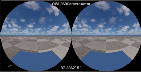
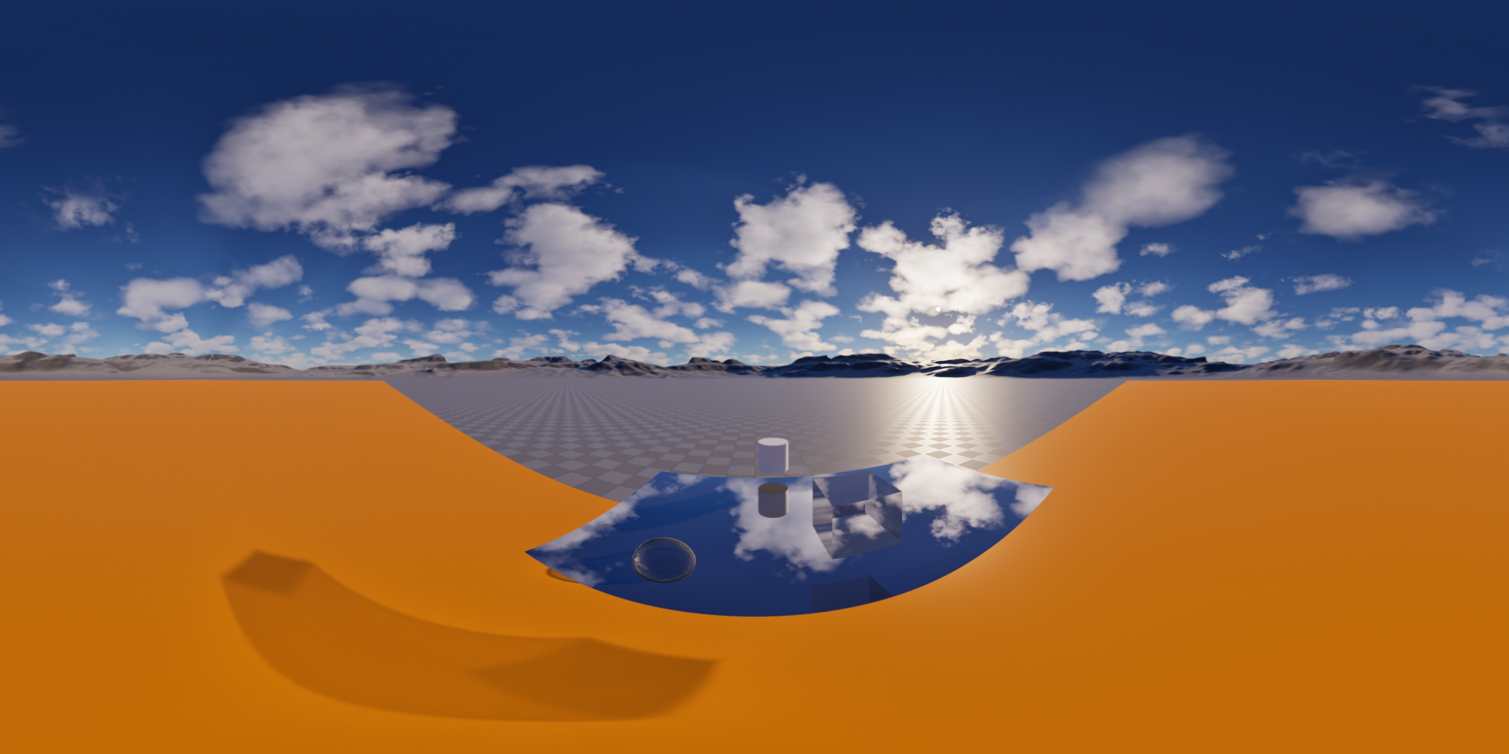
Stereographic (Tiny Planet)
This is a fun
projection typerecently used a lot in music videos, which shows the 360 output as a tiny, self-contained circular world.It’s very effective for showing 360 content in 2D social media formats like Instagram Reels or TikToks because it looks down onto the head of the talent from a viewpoint above.
You adjust the
FOVvalue which, set by default to120 degrees,to make the sky proportionally larger than the circular planet.
Cylindrical
This
projection typeis designed for cylindrical venues like gas tanks, concert halls or arenas and shows the 360 content as it would be seen if looking through the walls of the cylinder.
You can customise the
Vertical and Horizontal FOV,depending on the height of the walls and if your are projecting onto a whole cylinder or just a partial one:Some recommended
Vertical FOVsettings depending on the scale of the Cylinder (Height : Diameter):
Stereo Cylindrical
This is a
stereoscopicversion of thecylindricalprojection typeand can be used for VR experiences or live stereo experiences.The two eyes are rendering in a side-by-side format:
You can customise the
Vertical and Horizontal FOV,depending on the height of the walls and if your are projecting onto a whole cylinder or just a partial one.The current
stereoprojection can have seams above a90 degreevertical FOVvalue (used for a1:1ratio ofheight:diameter) so you may want to keep theFOVwithin that value.
Custom Mask Projections
In the
Advancedsection below, you can add anOutput Maskand adjust theVertical and Horizontal FOVto only render the specific pixels you need:This is availabe for
monoandstereoscopicformats such asEquirectangularwith customFOVsettings shown below:
Render Target
Render Target Output
You can capture the output of the camera to a
Render Targetfor previs, live-streaming or adding to aMaterial.Either add an existing one or go to
Create New Asset>Render Targetto make a new one.Adding a
Render Targetwill render a separate output from your UnrealViewportso you will see a decrease in yourFPS,you can usePause RenderingorCapture on Movement Onlyto manage this: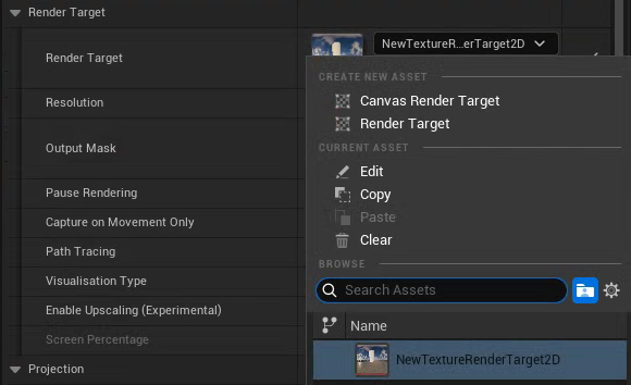
Resolution
This sets the
Resolutionof theRender Targetwhich is capturing the live output of the360 Cameraand the editorPreview.The
Resolutionautomatically matches the aspect ratio of your selectedProjection Type.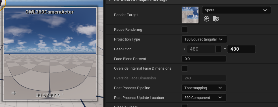
For previz, it’s better to keep this value small, because it consumes a lot of VRAM, unless you want to stream to a headset for live-previewing a sequence.
This value isn’t used for your
Movie Render Queueresolution which has separate settings: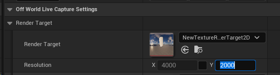
Output Mask
To add a fully customized crop to your render, you can use the
Output Mask.This requires a
PNGtexture in black and white, with black being the intended masked area, which you can drag into yourContent Browser: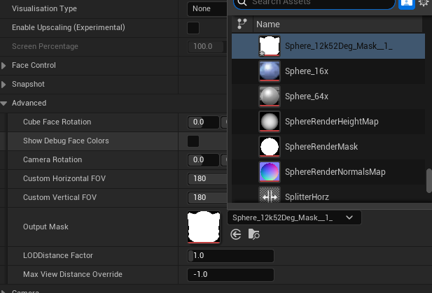
Then select the
Image Texturefrom theOutput Masksection, which will then apply the mask to your selectedProjection Type.You can adjust the
Field-of-Viewsettings to only select the pixels you need for your mask and then useAuto-Calculatein theFace Controlsection to render only those pixels:
Pause Rendering
Pause Renderingis used to stop theRender Targetfrom capturing the camera.When ticked you will see the camera preview also show a pause sign:

Capture on Movement Only
Capture on Movement Onlyis a performance optimisation which lets you keep the Render Target unpaused.It only updates the image when you move the
360 Cameraor change a setting in theDetailspanel.It’s recommended to use if you are working with the camera for previsualisation because you can see all your changes but won’t use rendering resources to render every frame.
If you are streaming from the
360 Camerathen you need to keep this setting unticked or your output will be frozen: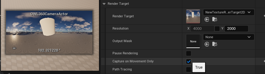
Path-Tracing
Path Tracingpreviews in yourRender Targetyour scene as it would look in the path-tracer, which can be useful for render previz.If you have a high
Resolution, it will take some seconds for the final image to emerge.You can use the path-tracer in combination with the
Snapshotfunction to capture the output to a png.This setting only affects the Render Target, if you are rendering path-traced output then you will need to use the Movie Render Queue settings.
Visualisation Type
If you are outputting
Stencil Layersfor color grading, you can use this to preview the different layers:
Upscaling and DLSS
NVIDIA Streamline/ Frame Gen doesn’t work with OWL tools and we recommend not to include it in your active Plugins when using OWL.
We recommend to only include these plugins if you want to use DLSS with OWL:

Enable
Upscalinglets you increase performance by using AI upscaling to render a%of the pixels in your output:
This is much more effective at higher resolutions where the total number of pixels to be rendered is much greated.
Generally, at around
70%in4Kyou will see a significant performance improvement without major artefacts.By default, the AI upscaling method used is Unreal’s
TSR (Temporal Super Resolution)but you can also use NVIDIA’s DLSS or other upscaling solutions, which will work automatically when you enable them in the Engine:
If you want to use
DLSSyou need to select these options after installing and activating the plugin in yourPluginssection in Unreal. IfDLSSis installed it will overrideTSR/ any other anti-aliasing setting in yourProject Settings: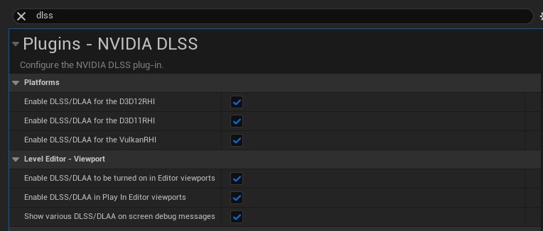
You may see a difference in performance between
TSRandDLSS(including different visual artefacts).
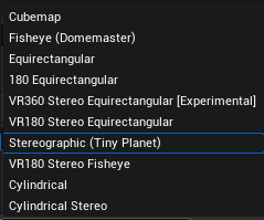
Projection
Projection Type
You can select between the following:
Most projections have adjustable
Field-of-Viewsettings, explained in theAdvancedsection below.All
stereoscopicprojections have an adjustable stereo eye separation setting which sets the Interocular Distance (between the eyes) with a default value of6.5(in default Unreal world units = 6.5cm):
Both
Fisheyeprojections controlFOVvia theDome Anglesetting, set by default to180 degrees,which narrows or widens the peripheral content included.You can also adjust the lens distortion of the Fisheye projection, once you have calibrated your lens following a guide like this (we recommend to use the C++ approach here as it will actively perform the calibration values).
which is required if you are compositing content with real-world footage using the
OpenCVstandardK1-K4settings: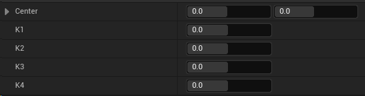
Center (X, Y):Modifies where is the precise optical center of the lens distortion projection.K1:Determines the baseline amount of spherical bulging "barrel" (negative values) or stretching out "pincushion" (positive values) across the bulk of the image.K2/ K3:Act as fine-tuning controls, correcting for secondary curves in the glass, ensuring that straight lines that start bending near the middle don't suddenly buckle or flatten out unnaturally.K4:Handles the steep mathematical drop-off at the perimeter, fixing edge-warping without ruining the look of the center of the image.
The
stereographicprojection controls FOV via it’s own setting, set by default to120 degrees,to make the sky proportionally larger than the circular planet:
Horizontal and Vertical Field-Of-View
Changing the
HorizontalorVertical FOVwill narrow the range of the projection.This can be used for custom shapes, cylindrical etc.
For example, the
Equirectangular 180projection has theHorizontal Field-of-Viewset to180 degreesinstead of360 degrees: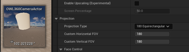
Face Control
This setting lets you control which pixels are rendered in your projections.
It will automatically update depending on the
Projection Typeyou select above, but you can also manually adjust it if you need.If you change the
HorizontalorVertical Field-Of-Viewsettings in theAdvancedsection below, you can clickAuto-Calculateto adjust how much of each-face is rendered to match your settings.Resetwill turn all the faces back on again.For example see in this
Domemasterprojection, one face is off and four faces only are rendering half the pixels as only this is required to produce the Dome output.
Show Debug Face Colors
This lets you see the position of each of the cube faces that make up your render so you can use the cube face rotation, camera rotation or other settings to adjust them:

When you are using an
Output Maskthe debug face colors will show you theHorizontalandVertical Field-Of-Viewsettings that are optimised to your required pixels.You can then use the
Face Controlsection to only render the pixels you need.
Camera Rotation
Setting a
Camera Rotationvalue can enable you to rotate the 360 output of your image while leaving the actual camera transform unchanged.This can be helpful for creating keyframed animations, then editing your output at a later stage for a specific output format.

Cube Face Rotation
This lets you rotate the cube faces from which the 180/ 360 projections are generated.
This rotation can be key-framed in
Sequencer.This can be beneficial for:
Eliminating seams (in the case of post-process effects like Bloom)
Keeping the most prominent feature in the correct viewing point of the audience or VR viewer.
Rendering driving plates by positioning the cube face edges at the horizon line.
Seam Management
Face Blend Percent
This setting creates an overlap between the different faces seamlessly blending the
pixels:
You should use it to manage seams which can occur with screen space effects like Bloom, Particles, Volumetric fog etc.
The recommended setting is
2-5%.You should also use this with
Stereoscopic 360to create a seamless render.
Post-Process Pipeline
Pipeline
The standard Unreal rendering pipeline is the
Tonemappingoption which will give you colors that match the UnrealViewport(andMovie Render Queue):
If you are using a lot of Bloom in your output, you can select the
Seamless 360 Bloomoption.This utilises our seamless bloom algorithm but doesn’t include
Tonemappingso changes the colors.We recommend to use this only if you really need a lot of Bloom.
Source
This setting controls whether to follow the
Post-Process Settingsof theOWL 360 Cameraor a separate UnrealCamera: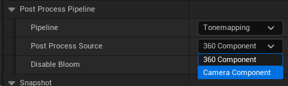
You will always see a
Camera Componentand anOWL360CaptureComponentas below:
If you are using the
360 Camera Actor, then we recommend you modify yourPost-Process Settingsin theOWL360Capture ComponentDetailspanel and select360 Componentin this drop down.If you are adding the
360 Capture Componentto an existing UnrealCinecamorCamera, then we recommend you selectCamera Componentin this drop-down in order to inheirit thePost-Process Settingsfrom that Camera.
In either case you can use a
Post Process Volumeand it will affect theOWL 360 CameraorCapture Componentas expected.If you modify an option in the
Post Process Settingsof the UnrealCameraorOWL Camera Component Detailspanel, it will override the setting from thePost Process Volume.
Disable Bloom
This is a tickbox to completely disable bloom in your render, in the case that setting a
Face Blend Percentdoesn't stop seams.Bloom is the most problemative post-process effect because it can have a very wide spread across your image.
If you need a light source with high Bloom another option is to use
Cube-Face Rotationbelow to keep it within a single cube-face from the360 Camerawhich stops artefacts appearing when the light source crosses the edges of the different cube faces.
Snapshot
Output
Snapshotwill instantly generate apngfrom theRender Targetof what the camera is seeing at that moment in time.You can set the
NameandDirectoryyou want for when it is generated: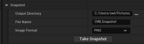
Snapshot can be generated from within Editor, Runtime or Packaged and works with both
LumenandPath-Tracing, as well asalpha channel.
Settings
You can configure the settings and metadata that go with the
Snapshotin theAdvancedsection:
If you see flicker or the lighting not correctly resolving then add
Warmup Frames.
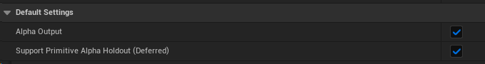
Alpha Settings
Alpha Output must be ticked in Project Settings to enable alpha channel, otherwise the pixels will be black (alternatively use CVAR r.PostProcessing.PropagateAlpha 1).
If you remove an Actor from your scene which has particles or other effects rendering over it, those will also be removed because of how Unreal’s render pipeline works.
If you are using Movie Render Queue, then it’s better to use Stencil Layers because they will have completely accurate colors and post process effects.
Show Only
The
Show Onlylist allows you to selectActorsin your scene so only those are rendered (against an alpha channel background).You need to tick
Use Show Only Listfor this to work.
Invert Alpha
You can also
Invert Alphato create a mask:
Hide Only
The
Hide Onlylist removesActorsfrom your scene (such as the cylinder in the case below):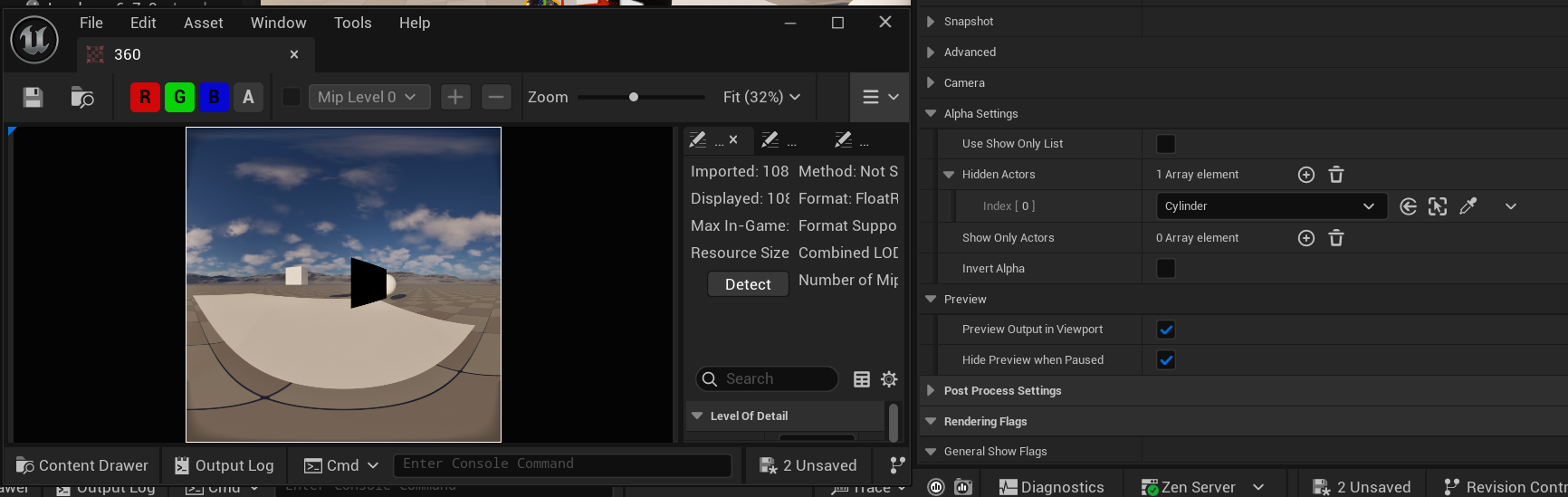
Camera
Near Clip Plane
Near Clip Planevalue can be increased if you automatically want to not render objects that are too close to the360 Camera.Near Clip Plane Follows Globaltickbox lets you follow your Project Settings.
Advanced
Override Internal Face Dimensions
If you want to increase detail and clarity your render (via super-sampling), it’s better to use the r.screenpercentage console variable with TSR enabled in Movie Render Queue because that includes temporal anti-aliasing.
This setting lets you increase the pixel density of the individual cube faces that make up your render so that you can render at a fixed resolution but get a level of detail that would otherwise only come with a higher resolution.
You can use this setting for previs of a static shot but for rendering we recommend the
screen percentageapproach above.
Preview
If the
Render Targetis unpaused, your preview window will automatically show the exact output of the360 Camera/ Component, including any modifications you have made: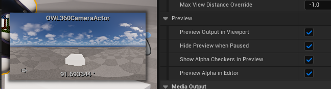
You can switch this off if you prefer.
Preview will also respect alpha channel if you have that selected.
Post Process Settings
When the
Post Process Update Locationis set to360 Component(see setting above), thesePost Process Settingswill be editable and will carry through to the final 360 render.Most
Post Process Settingswill not cause a problem for 360 renders, butBloom,Dirt Masksand other screen space based effects may need a significantFace Blend Percentageto work as intended.
Depth of Field
Depth of Fieldeffects can be achieved through thePost Process Settingsof theOWL 360 Camerausing theLens>Depth-of-Field>Focal Distancesetting: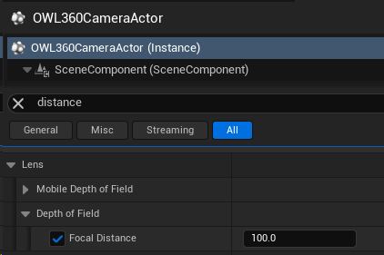
You should use this to chose the object in your scene that you would like to be in focus and then use the eyedropper to select it so that the
Focal Distanceof the360 Cameramatches the distance of that object.This will only work effectively if the object is in the foreground.
Render Flags
You can toggle these on/ off to preview the effect of different render passes in the
Render Target:This can be useful for de-bugging if seams are coming from certain post-process effects.

OCIO Color Management
Use the Color section to add OCIO configs to the 360 Camera Render Target to previs your content in the correct color space of your computer:
Set-Up
Enable the
OpenColorIO PlugininEdit> Plugins, restarting if prompted.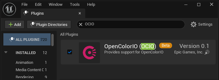
Right click in the
Content Browserand searchMiscellaneous> OpenColourIO Configuration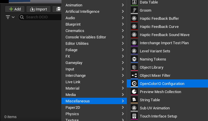
Color Spaces
In the OCIO Actor you can modify the input and output color spaces you want to use, as well as the config file that has the instructions on how to use them:
Configuration File:Unreal provides a lightweight version ofACESwhich may be sufficient for your needs but otherwise you will should replace it with a comprehensive library such as this (clickReload and Rebuildafter you have changed the file destination to your target library):
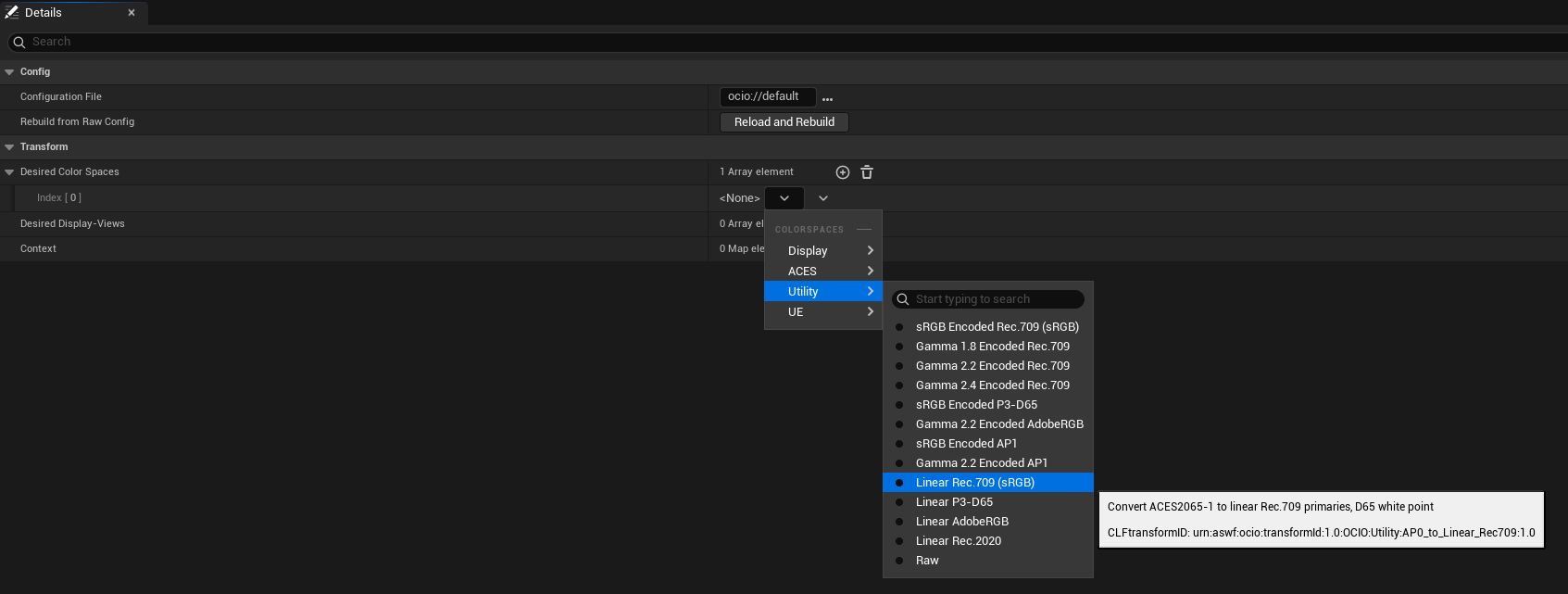
Desired Color Spaces:Is where you chose the color space you want to work in:Utility Linear Rec 709 sRGBis the default workingcolor spacefor Unreal Editor so you need this option as it will typically be what you convert from in your renders.If your monitor works in a different colorspace and you have already modified your
Project Settingsthen select that option instead.
If you are using the
ACEScolor workflow then you also should selectACES> ACEScgso you can select this as your output color space inMovie Render Queue.You can add other working color spaces here as well if you need (they can be selected between both in your preview and in your render settings).
Desired Display-View: Is where you select the color space of your monitor/s or display:sRGBis the standard for computer monitors and web content.If you have a specialist monitor/ display then you can select it from the list.
You can add more than one option here if you will be toggling between different color spaces. You can select between these in
Viewport/360 Camera/Movie Render Queue.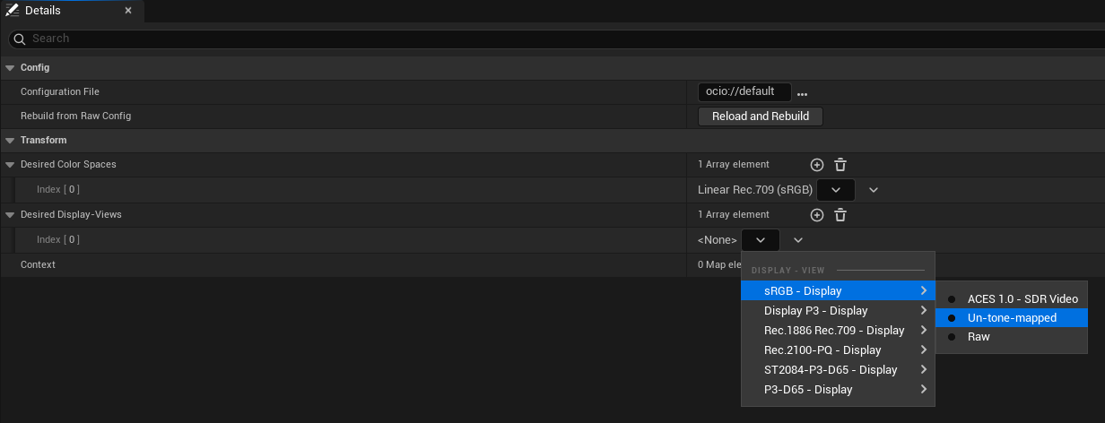
Context:This is an advanced setting which lets you define specific shots for which you want to use differentcolor spaces,this is normally reserved for high-end studio pipelines.
Config Actor
Load the
OCIO config Actorin theDetailspanel inColor>OpenColorIO Configuration,select the color spaces you need and then tickEnable OCIO:
If you haven’t selected
OCIOin yourViewport, you should instantly see the difference in colors in your360 Camerapreview:
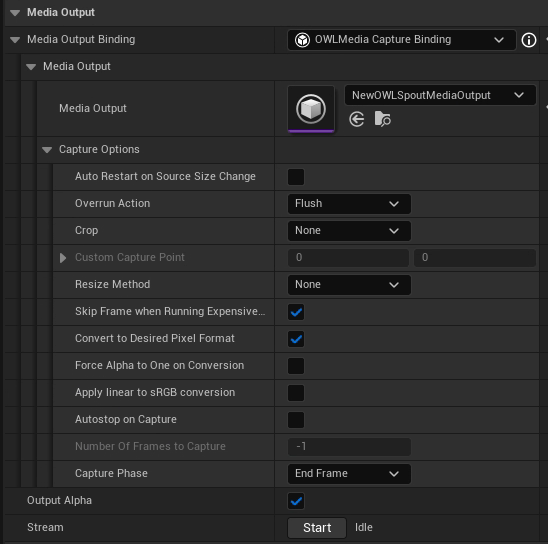
Media Output
The Media Output section combines Unreal and OWL media options making them all available to stream out video from the
360 Camera.This makes it extremely simple to output to Capture Card, Rivermax SMPTE 2110, NDI, Spout, Save-to-File, RTMP, SRT, RTSP, HTTP as well as many other formats.
This is very useful for content previsualisation but can also be used for live-streaming.
Audio is not supported via this method so if you need audio output then use OWL NDI Sender Manager or OWL Media Output Encoder.
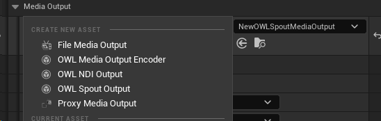
Output Type
Media Outputlets you select between different output options such as Spout, NDI, Media Output Encoder SMPTE 2110.You need to configure the Media Output Actor for any type you want to use by selecting it in the drop down and then opening it in your Content Browser to configure its settings:
Capture Options
These settings are inheirited from the Unreal Media Framework and can be used if required but in most scenarios won’t need modifying.
Stream
Once you have configured your options, you can click
Streamto initiate your output.This will continue streaming while you change
Detailspanel settings etc, which is useful if you are doing previz work.
Compositing
N.B. All cameras must have the same projection type for Compositing to work.
It is not possible to render multiple cameras to EXR layers while compositing is active, all cameras outputs are merged.
There is no cap on the number of 360 Cameras/ Components you can composite in Movie Render Queue but adding more with have an impact on V/RAM.
You can use the OWL
OWL 360 Compositing Trackin UnrealSequencerto composite between multiple360 Cameras/ Componentsfor effects like cross-fading.You can use this both in live-rendering and
Movie Render Queueto keep your complete workflow inside Unreal (rather than having to use external compositing or mapping software).However, in live-rendering, you need to manage the performance very carefully as you need at least two active Render Targets which will be very heavy on frame rate and VRAM.
Adding a Compositing Track
To perform a crossfade transition, start with two
OWL 360 Camerasin the level.These cameras can be in nested sequences, the recursion limit into nested sequences is
15.The
Composite Trackwill override yourCamera Cutsso the360 Cameras/ Componentsselected inside it will be rendered.
Ensure that both
360 Camerashave been added to your sequence:
Click the
Add Trackbutton on the top left of the sequencer in the top level sequence and addOWL 360 Compositing Track:
Once clicked you will see the
OWL 360 Compositingtrack with three buttons to the right:
Preview:(Play icon) Opens the EditorPreviewwindow to simulate the final composite.Refresh:(Recycle icon) Refreshes the list of360 Cameras/ Componentsthat can be added for compositing (in case you have added new ones) and automatically unbinds anyKeyframesections no-longer connected.Add:(Plus icon) Lets you add360 Cameras/ Componentsfrom this and nested sequences to your composite.
Composite Options
There are different compositing Blend Modes available, which you should choose depending on the content you are working with:

Over (Alpha Compositing):places the foreground layer on top of the background layer using the foreground's transparency.Use this for standard layering where you want one object to simply sit in front of another.
Multiply:looks at the color information in each channel and multiplies the base color by the blend color. The result is always darker. Multiplying any color with white leaves the color unchanged; multiplying with black produces black.Use this for adding shadows, creating "stained glass" effects, or removing white backgrounds from line art.
Add (Linear Dodge):sums the color values of both layers. The result is always brighter. If the sum of the values exceeds the maximum (1.0 or 255), it clips to pure white.Use this for light effects like muzzle flashes, glows, lens flares, or sparks.
Subtract:takes the background pixel values and subtracts the foreground pixel values. If the result is negative, it simply becomes black.Use this for comparing two nearly identical shots to find differences, or "punching holes" in an image based on brightness.
Screen:is the inverse of Multiply. It flips the values, multiplies them, and flips them back. It results in a brighter image, but unlike "Add," it is much softer and rarely clips to pure white.Use this for compositing elements with black backgrounds (like smoke or fire) without blowing out the highlights.
Difference:looks at the color information in each channel and subtracts the darker value from the lighter value.Use this for alignment: If you have two identical images perfectly stacked, the result will be pure black. If they shift even slightly, the "difference" will glow, showing you exactly where they don't match.
Creating a Composite
Use the
Addbutton to select the360 Cameras/ Componentsyou want to composite, each of which will be added as asub-track: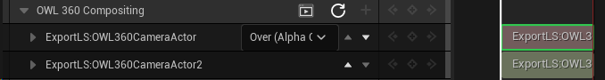
The order of the
sub-trackscan be changed using thearrow / caretbuttons.The bottom
sub-trackwill be composited last and eachsub-trackabove it next.
If you want to change the order of the
sub-tracksbut not change the order of theKeyframes(below) you will need tounbindtheKeyframes(rebindingtheKeyframesto other cameras will then automatically match the camera to thatKeyframe(see below).The drop-down in the top
Tracklets you select theBlend Modeyou want to use between the different360 Cameras/ Components: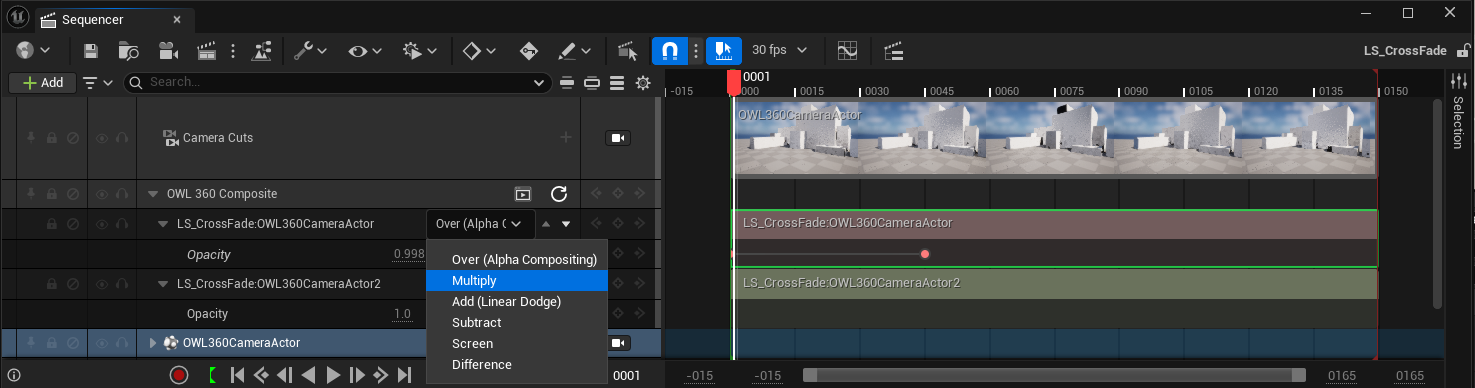
Expanding a
sub-track, reveals theOpacitysetting:1.0is completely opaque; and0.0is transparent.
You need to add a start and end
Keyframefor theOpacityof the topsub-trackto begin and end the composite.The start is normally value
1so that only the top360 Camerashows at the beginning of the composite:
The end is normally value
0so the top360 Camerais transparent (and the360 Camerabelow it will fully show):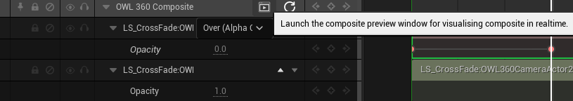
At the end of the composite, the sub-track below should have
Opacityvalue1(opaque), so its360 Camerais fully visible.
Always remember to save the
Sequenceso it can be picked up automatically in Movie Render Queue: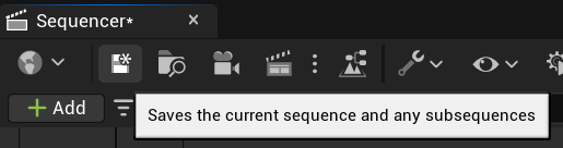
Previewing the Composite
N.B. All cameras must have the same projection type for Compositing to work.
Previewing multiple 360 Cameras/ Components will be performance heavy because you will have multiple Render Targets writing pixels.
To help this, you can Pause Rendering on the bottom camera (so it shows a static opaque frame) and just show the composite transition from the top camera.
Currently the Preview system is capped at 5 different 360 Cameras/ Components.
Ensure that all
360 Cameras/ Componentshave a uniqueRender Target: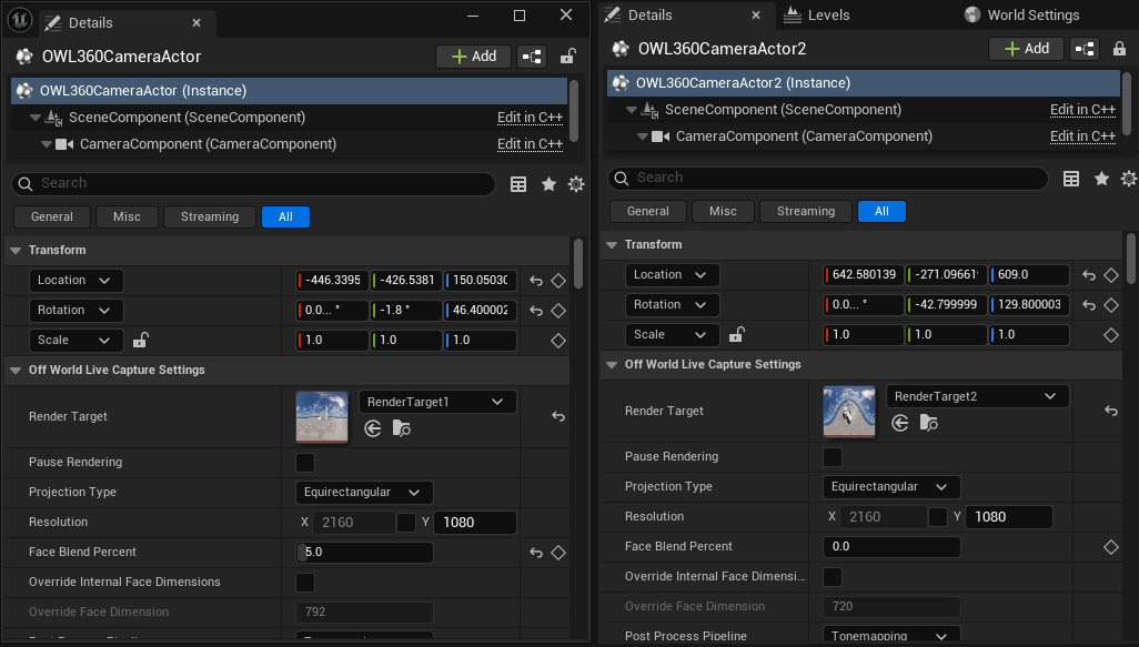
Use the
Previewicon to launch theComposite Preview Window:
Scrub the
Sequencertimeline toPreviewthe composite (for example in the image below you can see the bottom camera appearing at the end of the composite):
Change Composite Order
If you want to change the 360 Cameras/ Components in a composite but keep the Keyframe and Opacity settings, then you need to unbind and rebind them:
To unbind:In theSequencertrack right-click on theKeyframesection of the360 Camera/ Componentyou want to release/ move and select the optionunbind:
The unbound section will now show
Unboundbefore the360 Camera/ Componentname in both theSequencerand theKeyframe Tracks:
This track will be ignored at render time unless you
bindit to another360 Camera/ Component.
To bind:In theSequencertrack right-click on theKeyframesection of the360 Camera/ Componentyou want to reconnect and select the optionBind To:
You will now see that the
TrackinSequencerhas renamed to the360 Camera/ Componentyou just selected from theBind Tolist:
For example, in the Sequence above, OWL360CameraActor2 is now the top camera and so will be composited first (you will render this camera first and then reveal any cameras underneath it as the composite reveals).
Crossfading between Camera Cut tracks
You can use the OWL 360 Compositing Track alongside shot tracks to crossfade between multiple camera cuts or sub sequences. For this you will need to have at least two 360 cameras in your scene with matching projection types and resolutions.
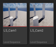
Create a level sequence for each camera cut that will be used:
Add an
OWL360CameraActorand aCamera Cuts trackto eachLevel Sequence, keyframe any camera movement or camera property changes within this sequence. Repeat this for the other cameras in their respective sequences: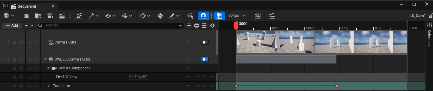
Create a
Master Sequenceto house anySubsequencesandCompositing Tracks. This sequence can also contain animation of any non camera elements in the final render:
Add a
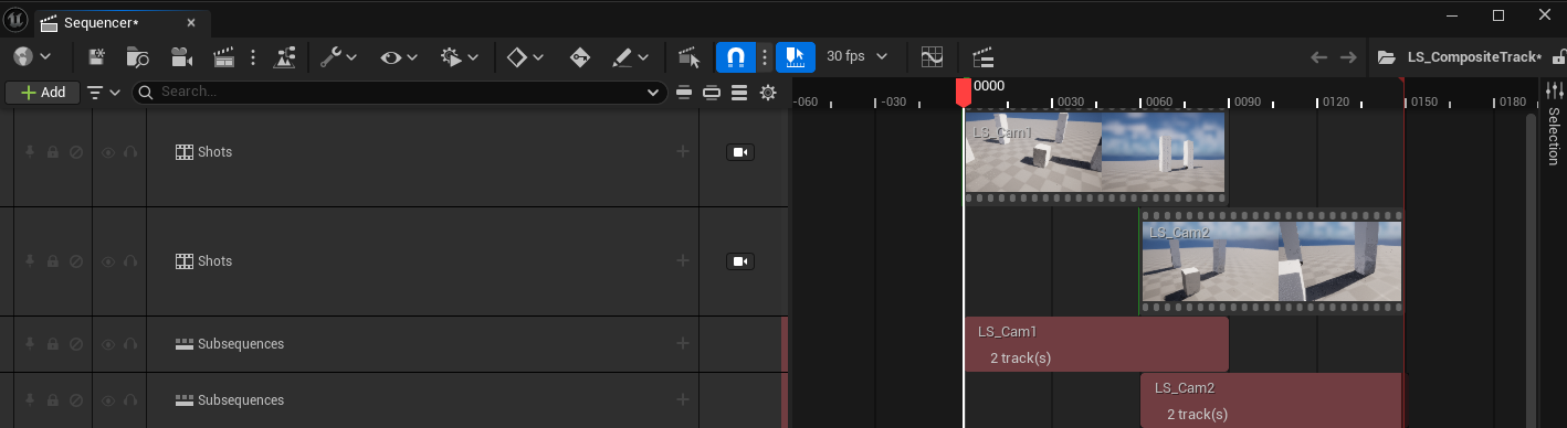
shot trackfor each of theSubsequencesto be crossfaded.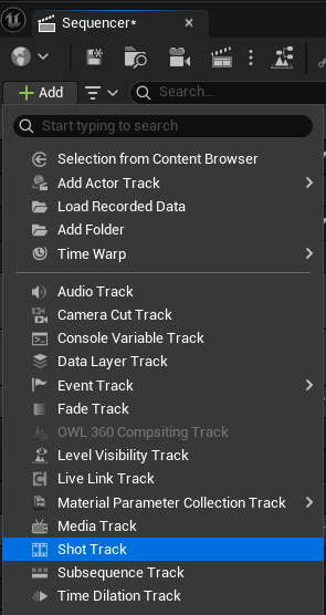
Position the
Shot Tracksabove each other, overlapping for the duration of the crossfade transition.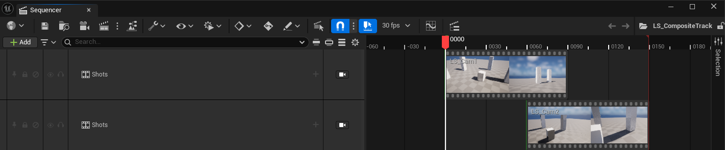
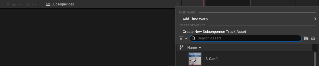
Add a
Subsequence Trackfor eachsubsequenceand position them at the same overlap as theshot tracks.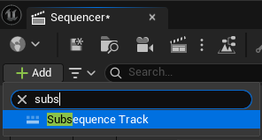
Add both
OWL360Cameraactors to the level sequence and create aCompositing Trackthat fades between the two: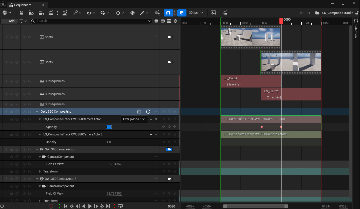
You can preview the
Compositeas explained above and then render theMaster Sequenceto render the full composite transition: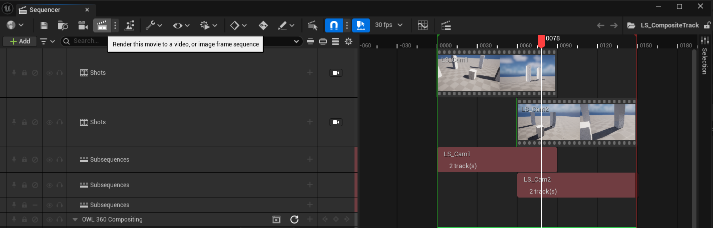
Camera Lerp Transition
Sometimes a camera cut blend is used to make one camera move from it’s location to a second camera’s and pass on the camera cut to that second camera.
To achieve this effect with a 360 Camera, a camera position lerp workaround can be used.
Add two
360 Camera Actorsto a sequence: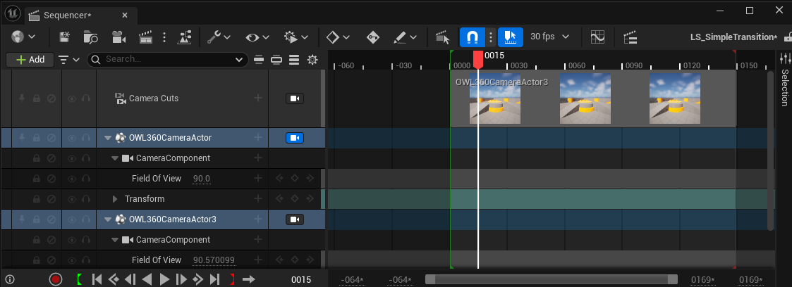
Create your desired
keyframesfor these cameras.Create a start and end
keyframefor thetransformof both cameras within aframe range, this will be the transition section of the sequence. For this example it is theframesbetweenframe 60and80.At the final frame of the transition (
frame 80in this example) ensure the transform values are the same for both cameras (this is the point of transition).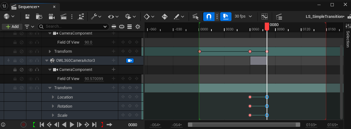
Add a
camera cutstrack for the second camera at the endkeyframeof the transition.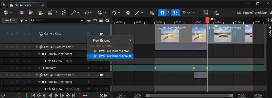
Lock the
viewportto thecamera cutstrack to preview the full transition from camera 1 to camera 2.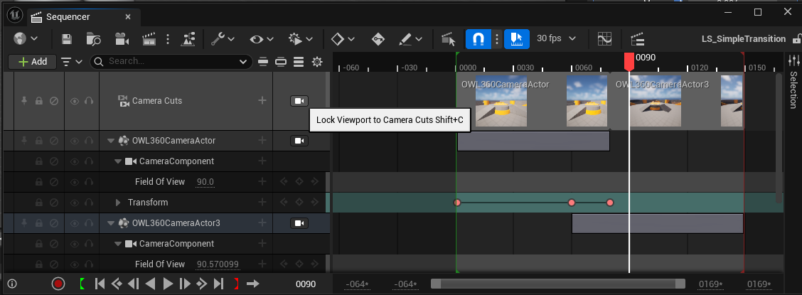
Trouble-Shooting
Seams
When you are using
LumenforGlobal Illumination, seams can appear at the edges of the cubemap which renders the raw pixels of the360 Camera. These steps should solve them:Face Blend Percent: Try this value at5%and then increase as required. It will eliminate most seams.Hardware Ray-Tracing: Change this setting in your Project Settings. This can reduce seams because Lumen relies less on screen space effects to generate lighting:
Cube Face Rotation: Using the Cube Face Rotation settings can prevent seams by ensuring that elements that affect screen-space effects are always positioned inside a face (see above).Turn off
Screen Traces: This fixes a lot of interior seams caused by bounce lighting.Find the
Post Process Volumein your scene, search forScreen Traces, then untick the checkbox.You may notice some
Global Illuminationis lost by doing this and your image will have a more stark contrast.
Remove
Meshes(that cause seams due toIndirect Lighting) fromLumenusing theMesh Detailspanel to disable one of the following:For
Software Ray Tracing, uncheckAffect Distance Field Lighting.For
Hardware Ray Tracing, uncheckVisible in Ray Tracing.You can also separate complex objects in your modeling software to ensure that Unreal Engine can shade them more accurately, which can improve Lumen reflections and reduce seams.
Add
Temporal Anti-Aliasing Samplesto fast-moving imagery to remove seams and improve shadows and reflections.
Exposure
When you drop the 360 Camera into your scene it can be over or under exposed compared to your Viewport.
Exposureis set toManualby default to avoid seams and artefacts caused byAuto Exposure.The
360CameraActorautomatically sets anExposure Compensationof10when brought in to a level.This can be too high or low for some scenes.
Adjust this setting in the
Post Process Settingsusing theExposure Compensationslider:
Post-Process Effects
For tips on how to deal with Bloom, Particles, Volumetric Fog, God-Rays, Water, Dirt Masks etc. please see the separate workflow article.
Frame Rate Drop when in Background
By default, Unreal throttles the CPU when Unreal is in the background vs other software which causes the frame rate to drop.
To change this, go to
Editor Preferencesand untickUse Less CPU when in Background: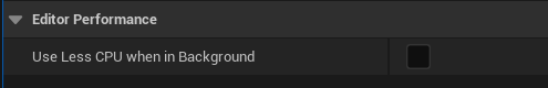
Audio not Playing when Editor in Background
By default, Unreal will stop audio playing when the Editor is in the background vs other software.
To change this, pick the Engine version you need in your
File Explorerand go to the file path:
In
Configgo toBaseEngine.iniand open the notepad: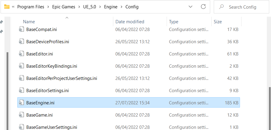
Search for
UnfocusedVolumeMultiplierand change the value from0.0to1.0: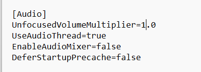
Save the file and close and re-open Unreal.
Your audio will now play continuously no matter if Unreal is in the background or minimised.