VFX and Post-Process Effects in 360 Degrees in Unreal Engine
How to seamlessly render VFX and Post-Process Effects in 180 and 360 Degrees in Unreal Engine such as Particles, Volumetric Fog, Dirt Masks, Water, Bloom, Lumen and others.
Last updated About 2 months ago
Overview
When rendering from the 360 Camera/ Component, some VFX and post process effects have to be customised to ensure a seamless output.
In many cases, the issue is screen space effects that are used in Lumen for rendering speed optimisation and clash with the cube faces of the cameras that create the 180/ 360 output but there can also be issues with the behaviour of global illumination effects which need time to settle or work differently at different resolutions.
In almost all cases these seams can be dealt with via the tips below. In the extreme circumstances that they don’t you can use path-tracing which will render much more slowly but doesn’t suffer from screen space issues.
Lumen
When you are using Lumen for Global Illumination, seams can appear at the edges of the cubemap which renders the raw pixels of the 360 Camera. These steps should solve them:
360 Camera Settings
Face Blend Percent: This will overscan the different cube faces and then blend them together at the edges to remove seams.Try this value at
2.5%and then increase as required: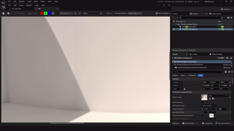
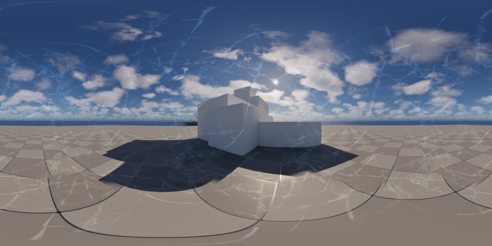
Cube Face Rotation: Using theCube Face Rotationsettings can prevent seams by ensuring that elements that affect screen-space effects are always positioned inside a face (see guide inOWL 360 Cameradocs): This is very useful for keeping a specific content feature within a single cube-face:For example, there is a clear seam at the bottom of the cylinder here:
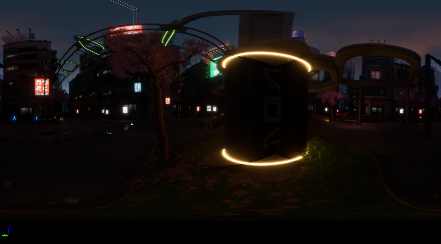
Using
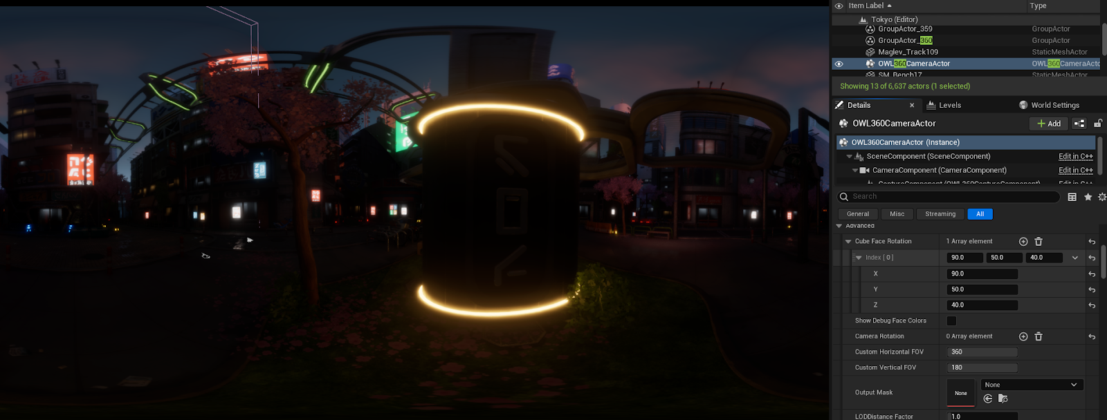
Show Debug Face ColorsandCube Face Rotationposition the seams so that they do not cross the emissive material: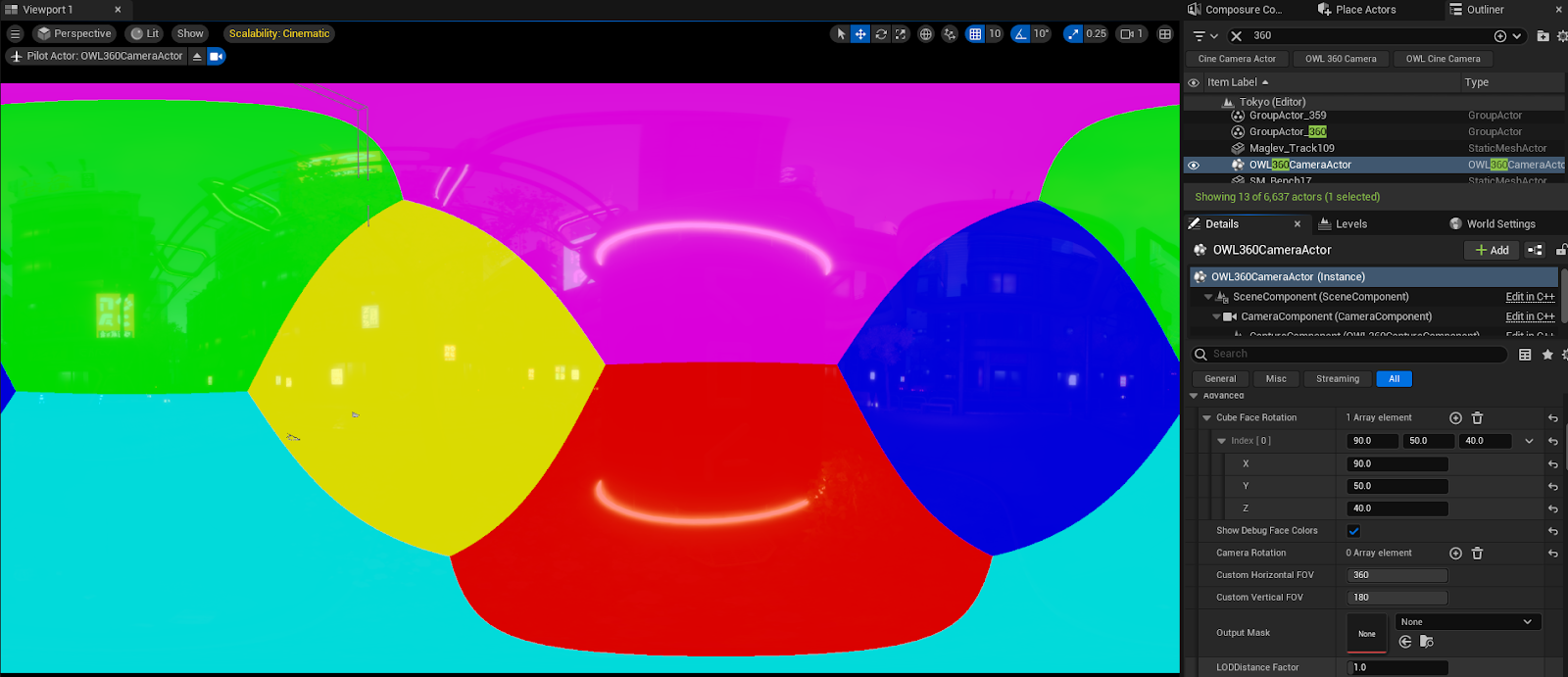
Now the seams will be invisible:
Unreal Settings
These settings will have a significant impact on the Global Illumination in the scene and should only be used if the Face Blend Percentage doesn’t solve your issues.
Hardware Ray-Tracing: Change this setting in your Project Settings. This can reduce seams becauseLumenrelies less onscreen spaceeffects to generate lighting: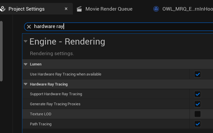
When camera movement or lighting changes are fast, some
Global illuminationseams can be caused byLumen Final Gather Update Speed.Raise the
Lumen Final Gather Update Speedto decrease the time it takesLumenLight changes to propagate to the final image at a performance cost:
Local Exposurecan causeglobal illuminationseams:Add the
Console Variabler.LocalExposurewith value0toMovie Render Queueto remove these.You should test this in
Editorfirst to check the impact on your lighting. You may need to make adjustments to get a similar image once the seams are gone.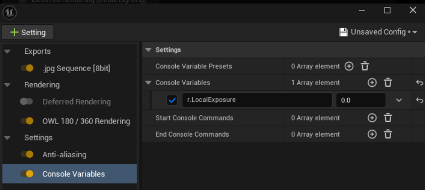
Turn off
Screen Traces: This fixes a lot of interior seams caused by bounce lighting.For the
Post Process Volumeor the360 Camera Actorin your scene, search forScreen Traces, tick the left checkbox to enable the setting, then untick the checkbox to disableScreen Traces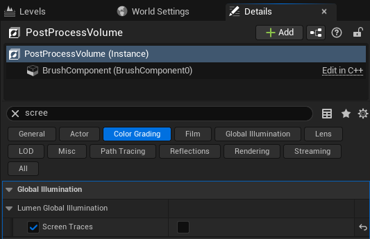
Remove
Meshes(that cause seams due toIndirect Lighting) fromLumenusing theMesh Detailspanel to disable one of the following:For
Software Ray Tracing, untickAffect Distance Field Lighting.For
Hardware Ray Tracing, untickVisible in Ray Tracing.You can also separate complex objects in your modeling software to ensure that Unreal Engine can shade them more accurately, which can improve
Lumenreflections and reduce seams.
Super Resolution
Raising
Screen percentagecan be a way to increase visual clarity or crispness because it gives the anti-aliasing algorithm more pixels to select color and detail from.This can can be used alongside high sample counts to balance fidelity and smoothness for the highest quality final output:
Ensure that you are using
TSRas youranti-aliasingmethod and then use theConsole Variabler.Screen.Percentageand set this to a value>100and<200: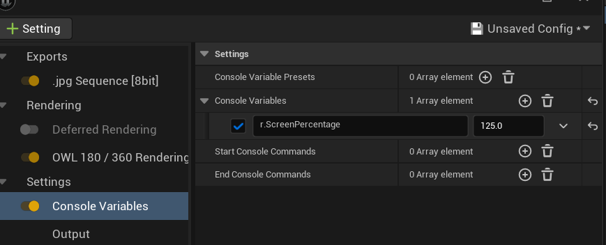
In this example, the left hand image is a
200%and the right100%screen percentage. Both have32 spatial samples. You can see a significant difference in the clarity of the foliage at the top of the image but in other places it’s much less obvious.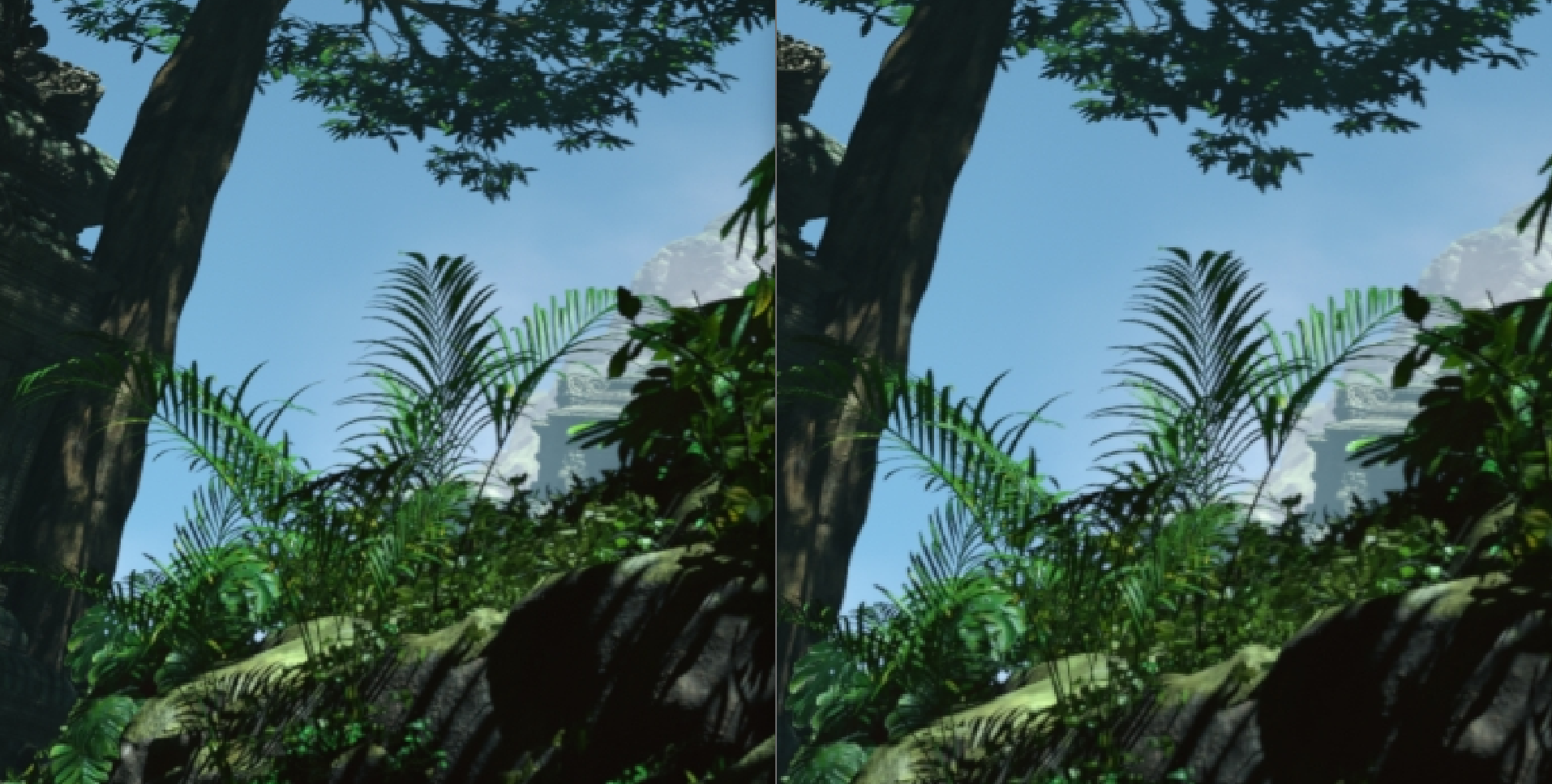
Increasing screen
percentagewill significantly increase your render times andVRAMusage so should be used carefully.
Particles
Niagarasystems andCascadeparticles useSpritesthat always face the camera which can create seams.This can be fixed by making the particles
Velocity Alignedinstead ofFacing the Camera.
You will need to make the changes below for all Particle Emitters in a system to reduce all seams. Mesh renderers do not need to be changed.
Niagara Systems
Go to any of the
Emittersin the system and in theirSprite Renderersection change theAlignmenttoVelocity Aligned:This means that the
Spritesnow turn based on their own velocity instead of always facing the camera.
N.B. If you have large Sprites you will start to see that they are 2D as they rotate at a 90 degree angle to the camera, but with smaller particles this is invisible.
Ensure that the
Boundsof the particles are large enough that they are captured by all of the faces of the360 Camera.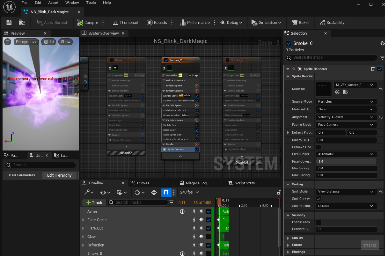
Niagara Clipping
Some Niagara systems can clip when the 360 Camera moves far away from them.
To fix this open the Niagara system and select the emitter. If the
Sim Targetis set toCPUSim, change theBounds modetoDynamic: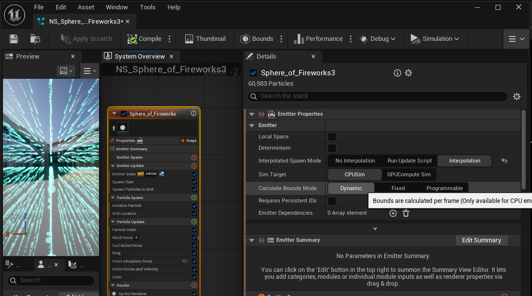
If the Particle System is
GPU Based, set theBounds ModetoFixedand raise theMax Radius: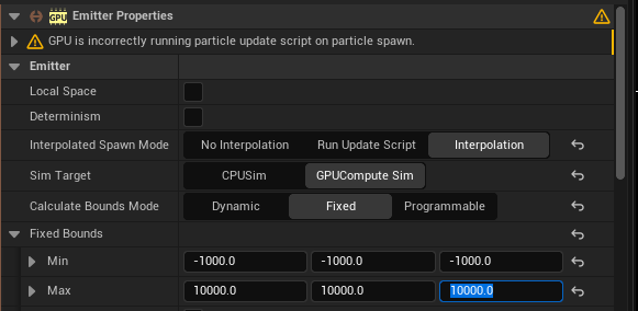
If GPU Particles still clip when higher bounds are set, consider switching to CPU Dynamic
If the Niagara System uses multiple
emitters, this setting will have to be set for each of them.
Niagara Determinism
When using
titlingwithhigh resolution rendering, random particles can appear differently across differenttiles.To fix this, particle systems need to be set to
Deterministicin the Niagara Emitter’sDetailspanel: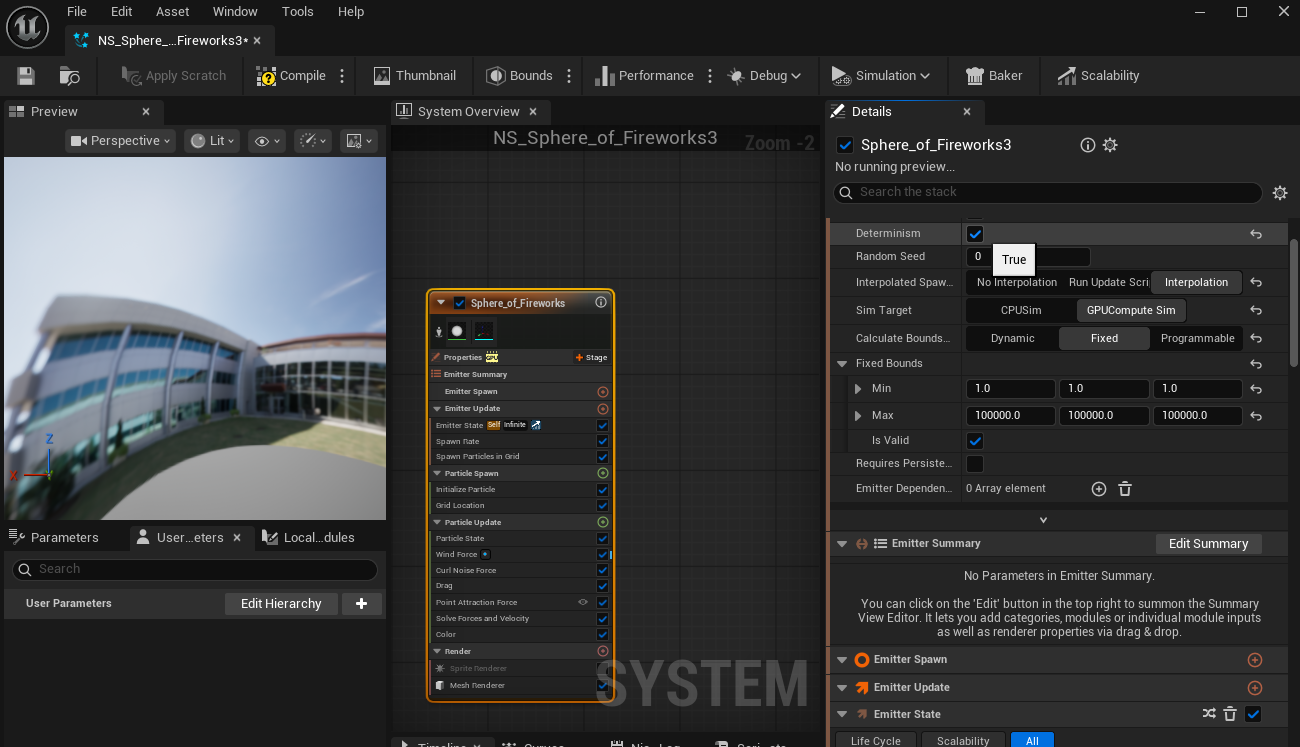
Cascade Systems
Change the
Screen Alignmentin theEmittersection inCascadesystems toPSA Facing Camera Distance Blend: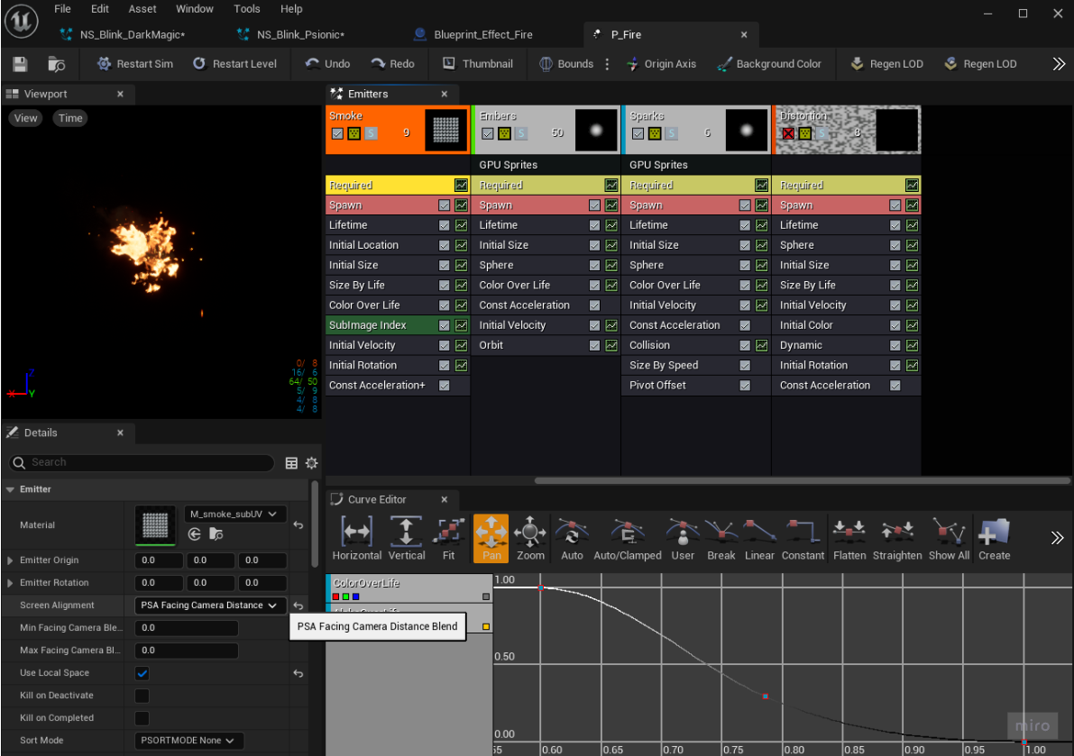
Chaos Systems
Chaos systems that use fractures and fields can have random results, so if making a tiled render, these systems can be give different results for each tile of a 360 render resulting in visible seams.
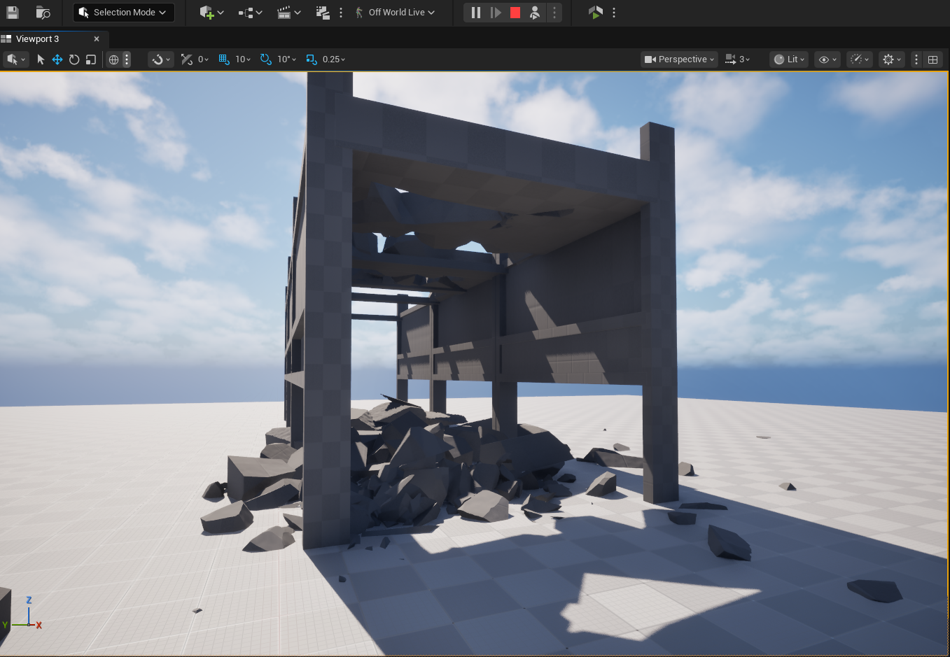
To fix this, creating a cached version of the chaos system will ensure that the it runs deterministically instead of randomly.
After creating a Chaos System, select the relevant geometry collection and chose
Actor >Chaos > Create Cache Manager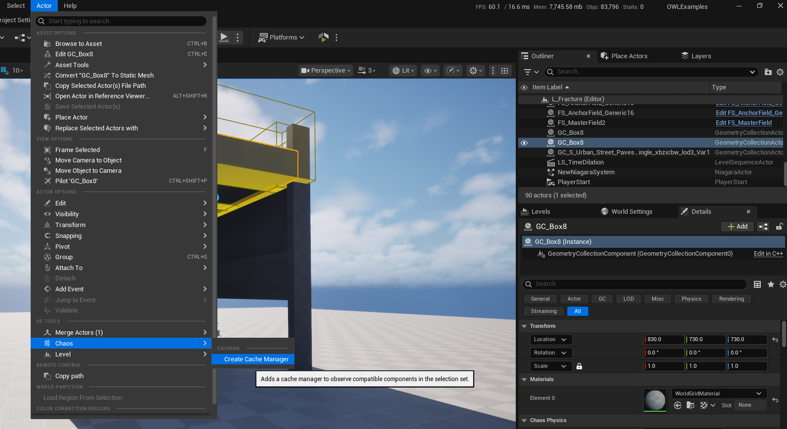
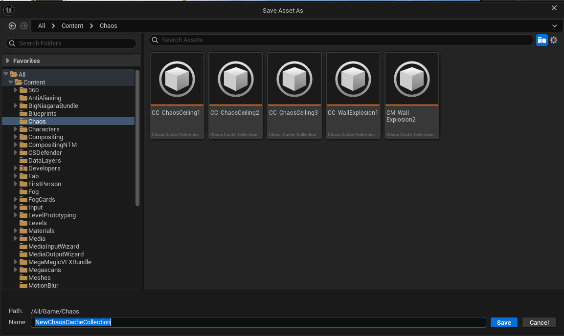
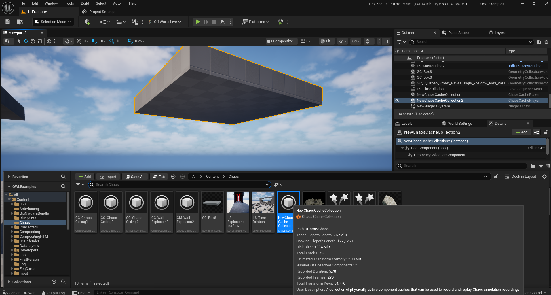
Save the new Collection in the Content Browser
Find the newly created
Cache Managerasset in the outliner, it should have theCache Collectionautomatically referenced in theCache Collectiondropdown.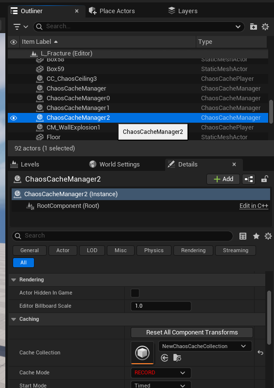
With the Cache Mode set to RECORD, press simulate to create a cached recording of the simulation. This step can be repeated to retry the simulation.

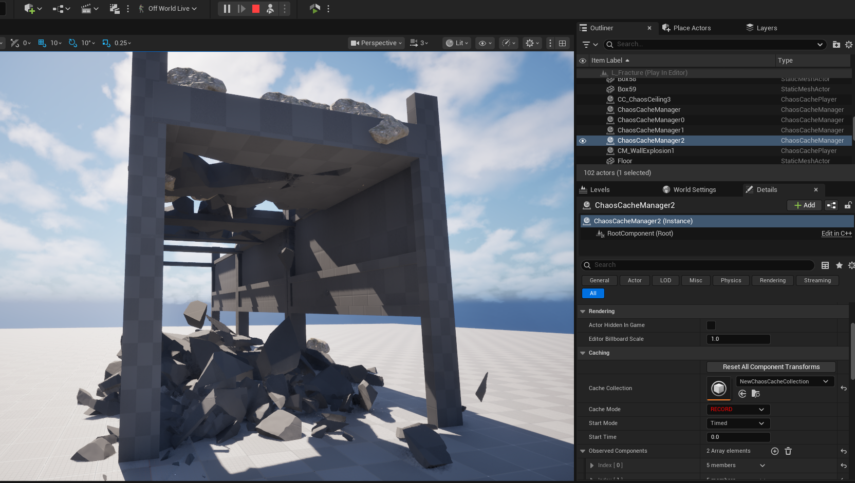
Drag the Chaos Cache Collection in to the level to replace the random fracture with a Cached system.
Volumetric Fog
Sometimes artifacts will occur only when the camera is moving, and the seams will clean themself up after a period of time. In this case you can use Anti-Aliasing to remove the seams.
Volumetric Fogcan cause seams becausevolumetric effectsare aligned to the camera frustum (the camera’s view) so the cubemap of cameras can have differences between them.Directional LightandSky Lightsettings can also cause seams withVolumetric Fogeffects.Follow these tips to remove seams:
In the
Detailspanel yourExponential Height FogActorset a value forFog Density(we recommend to start with4):
Fix the color by going to your
Sky AtmosphereActorand changing theRayleigh Scattering Colorto grey or white: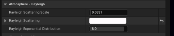
Make your fog more interesting by adding
Volumetric Fogin theExponential Height FogActor Details Panel: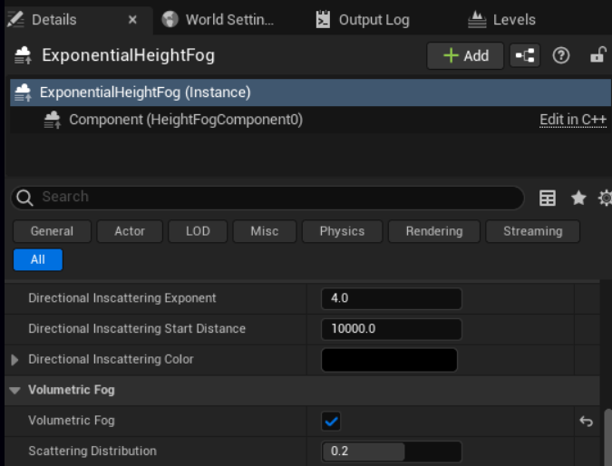
This may cause some seams in the shadowed areas where objects occlude the
Light Sourcesin the scene which can be fixed by going to theDirectional LightActorand uncheckingLight Shaft Occlusion: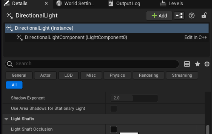
In more complex scenes where the
actorscover the sun more or have more complex shadows you may have scenes caused byAmbient Occlusion.To fix these, add a
Post Process Volumeas described here, then go toRay Traced Ambient Occlusionand set:EnabledtoTrueandIntensityto1: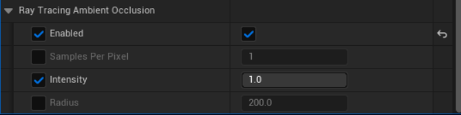
You will lose some lighting detail when enabling
Raytraced Ambient Occlusion.Some of the darker areas can be restored by increasing the
Ray Tracing Ambient Occlusion Radiusbut this can have a smudgy effect on the shadows so should be used sparingly:
If you don’t want to enable
Raytraced Shadows, you can also try disabling theCast Volumetric Shadowsetting in theSkylightwhich will reduce the contrast in the volumetric shadows:
With this these tips you can achieve seamless
volumetric foglike this: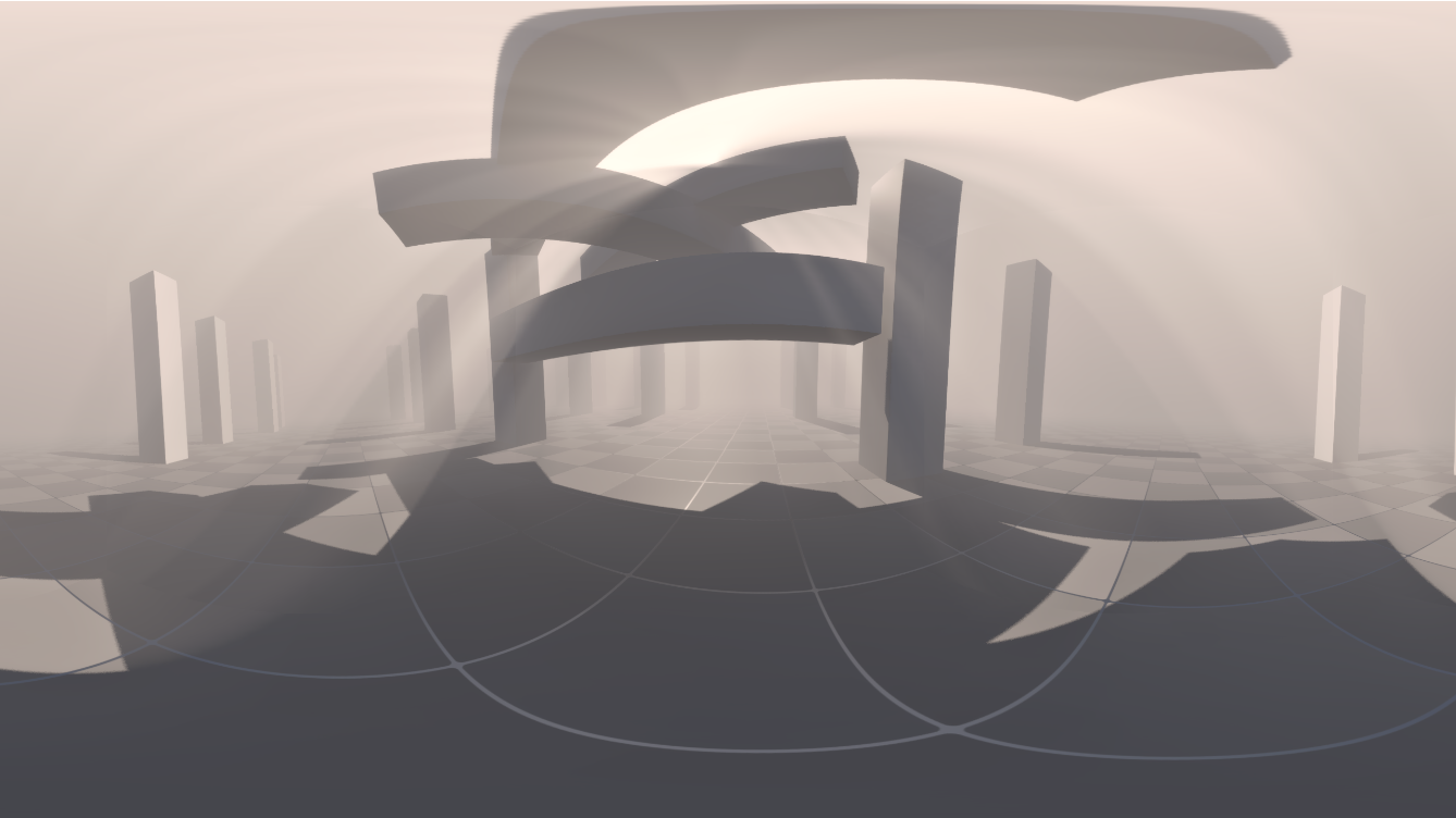
Light Shafts
Light shafts are based on the sensation of having light leaking through a surface’s gaps from above in a dappled God Ray effect.
Because this is based on a light ray being above the head of the of the viewer, it can create seams in the 360 camera cube map because each faces sees the light ray differently.
There are two suggested solutions:
Face Blend Percent
Add a
Face Blend Percentageof10which will soften the edge of thelight shaftenough for the seam not to be visible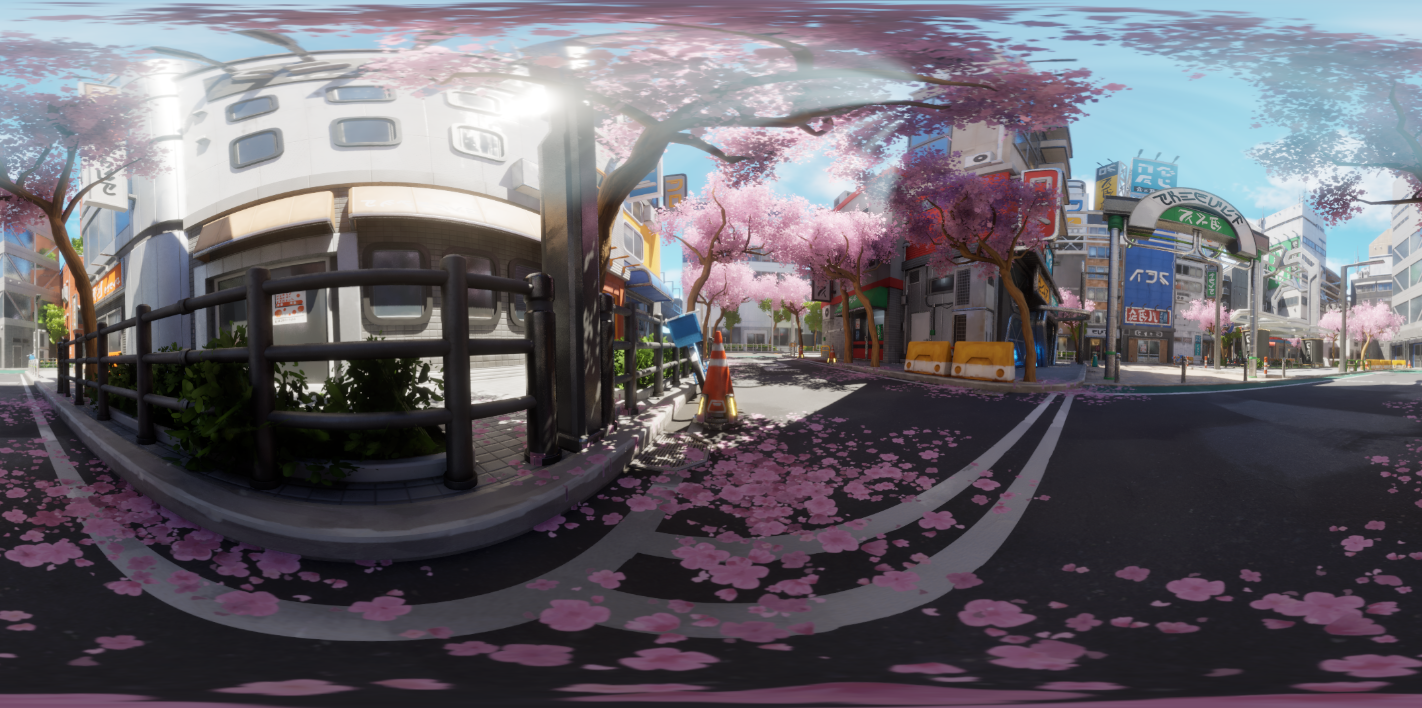
Fog Card Method
Fog cards are deterministic, meaning they will be the same every time a render is run.
This helps for art direction but also for tiled high resolution renders because will be no difference in the output for each tile.
If there is a
light shaftorFog Elementthat requires direct authoring such as alight shaftthat shines on to a particular object, or a fog element that need to be deterministicFog Cardscan be a good way to create this: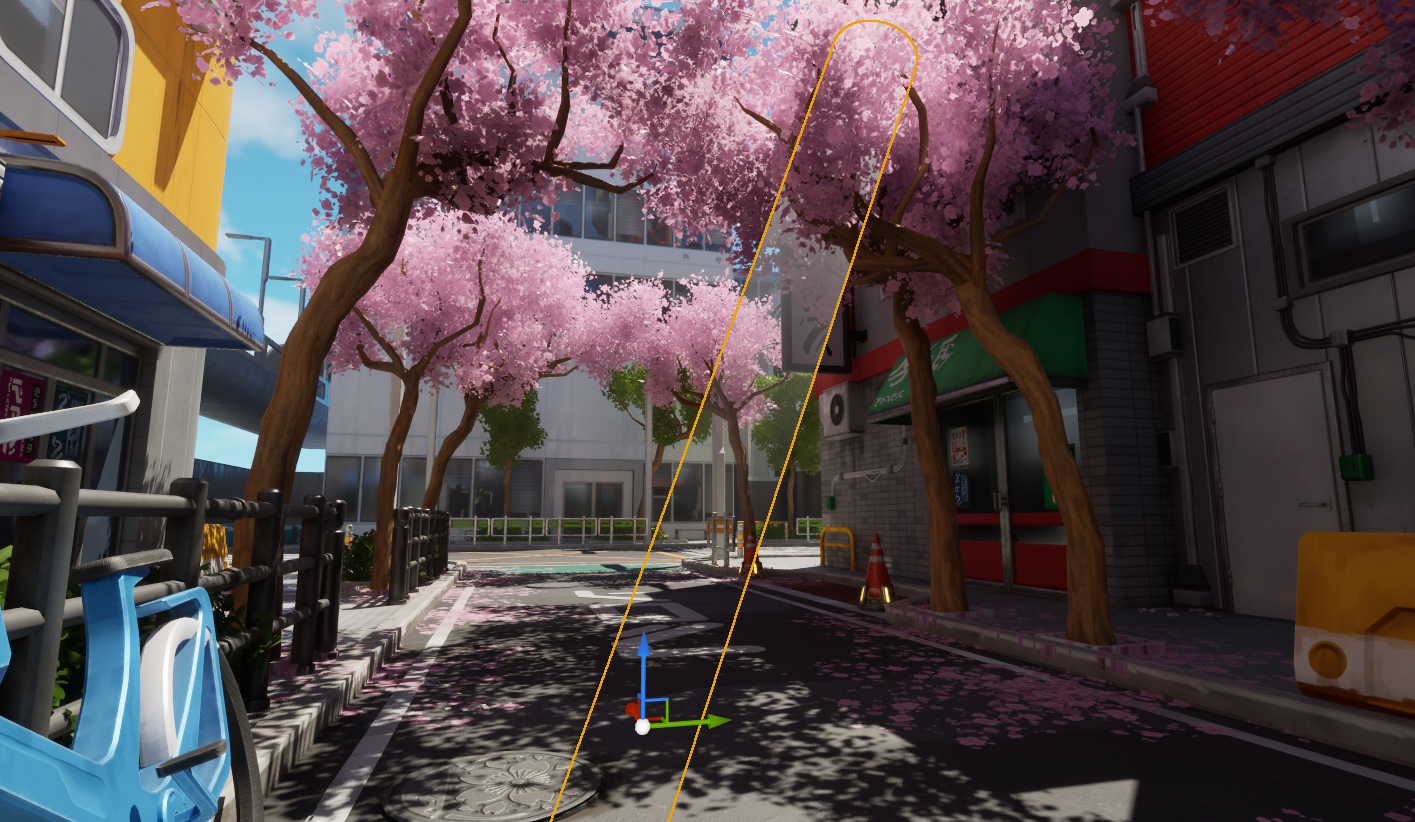
Fog Cardsare created usingTranslucent Materialson geometry such asplanes.The 2D nature of a
materialon aplanemeans that the fog effect can break if viewed from the side angle.So these effects are most effective when used as many very subtle layers, from a distance or combined with a depth based opacity to make them fade when the viewer is close to the geometry.
Excellent fog card materials can be lifted from the Dark Ruins Megascans Sample Level and other free example levels:
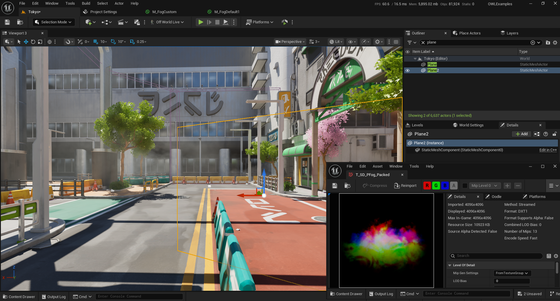
To create a simple
fog card, add aplaneto the scene.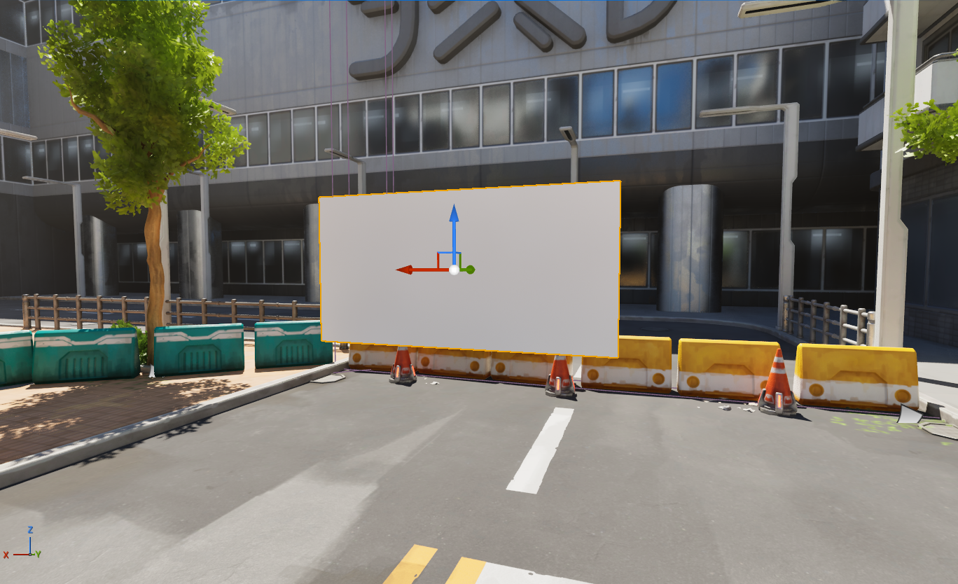
Create a new
Materialand set theBlend ModetoTranslucent, use anImage Textureand connect theAlphaorRchannel (if your fog is on a black background) to theOpacityoutput.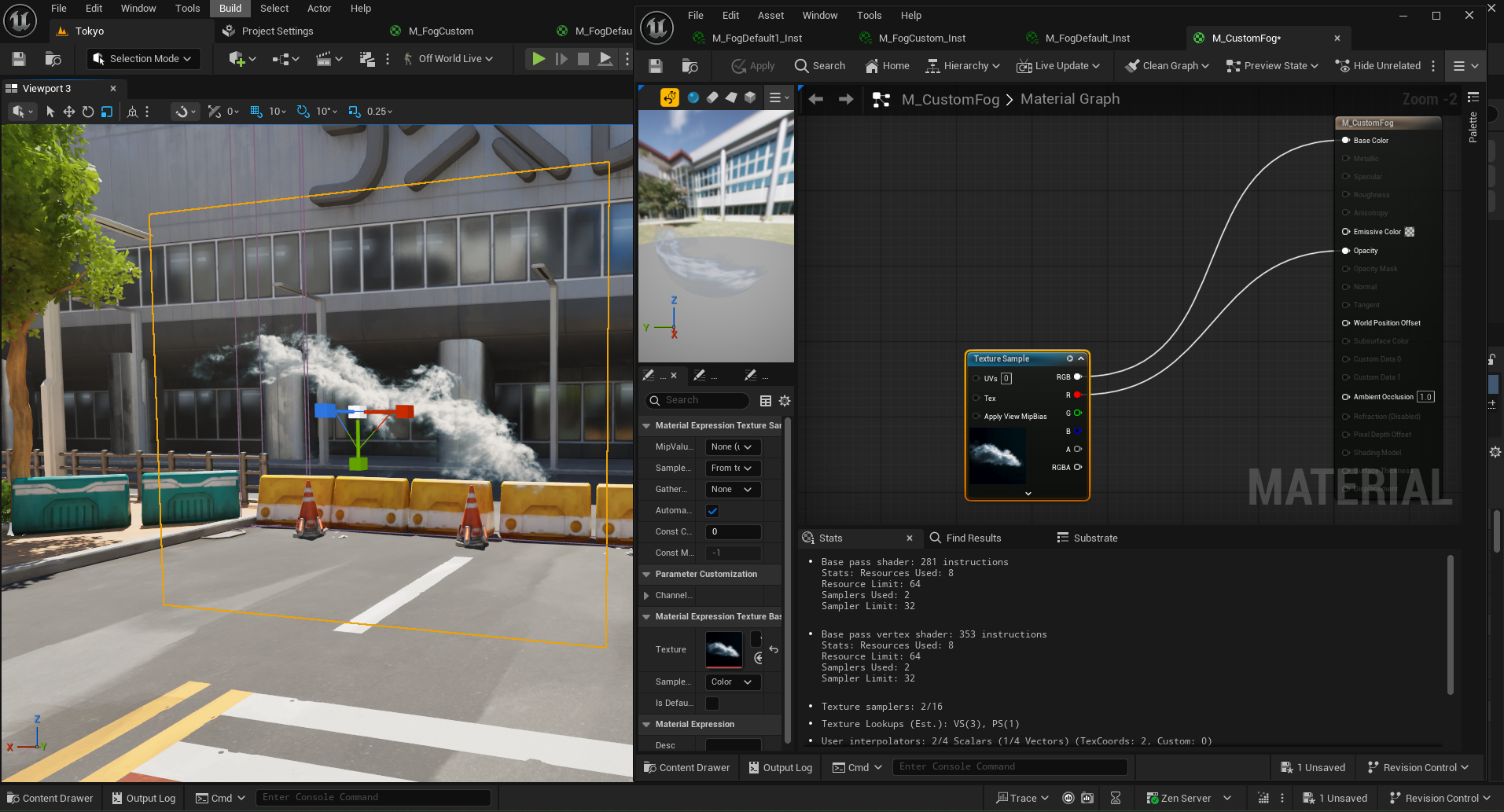
Use a
Color Rampnode to tweak theopacity.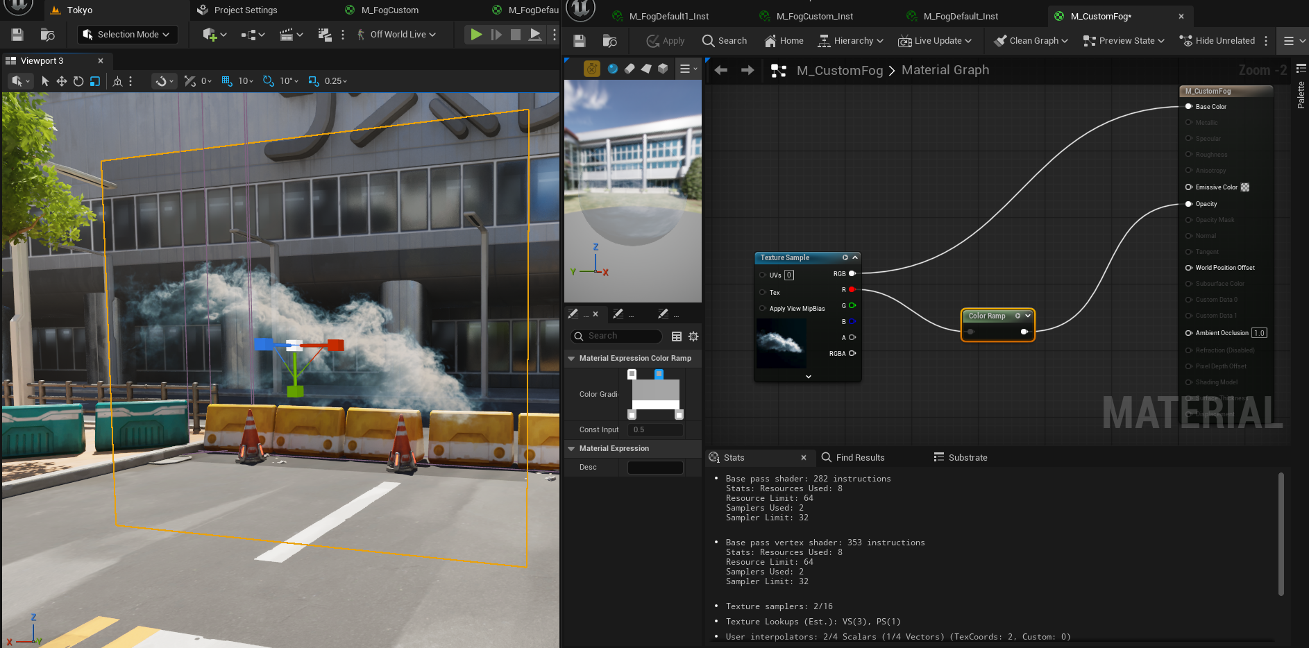
A flow map is a good way to add some subtle animation to a static texture.
The material from the Megascans Sample Level has a great flow map example.
Copy and pasting the
nodesmarkedflow map, followed by the section markedBase Colorcan be a way to add a flow map to your own custommaterial.An example of a simpler animated
fog cardcan be found here: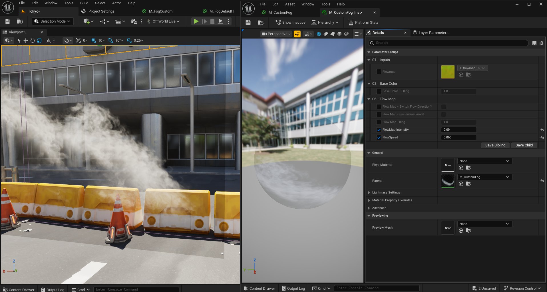
Copy this
materialfirst: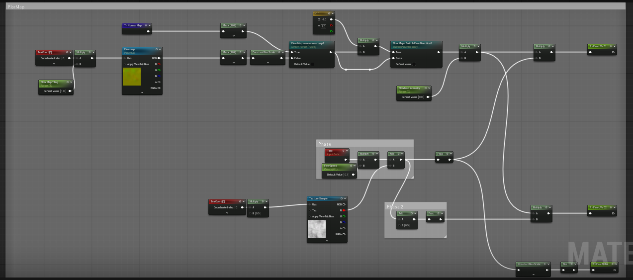
Then copy this material:
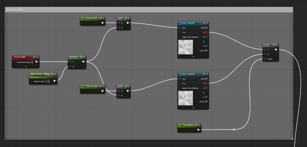
Finally, replace any of the
texture sampleswith your ownFog Texture.If recreating this
materialfrom scratch aflow mapwill need to be added, this is a simplenoise texture.
You can reference the
Depth Fading Fog Cardssection below to further improve thisFog Card Material.
Depth Fading Fog Cards
Fog cardswill clip and cause unwanted harsh edges when passed through like in this image:
To fix this, create a
distance based fade effectto control theopacityof thefog cardas the camera passes through it.
This Fog Material has a
Dynamic OpacityandDepth Fadenodesetup that can be connected to an existingAlphatexture through anMultiply node: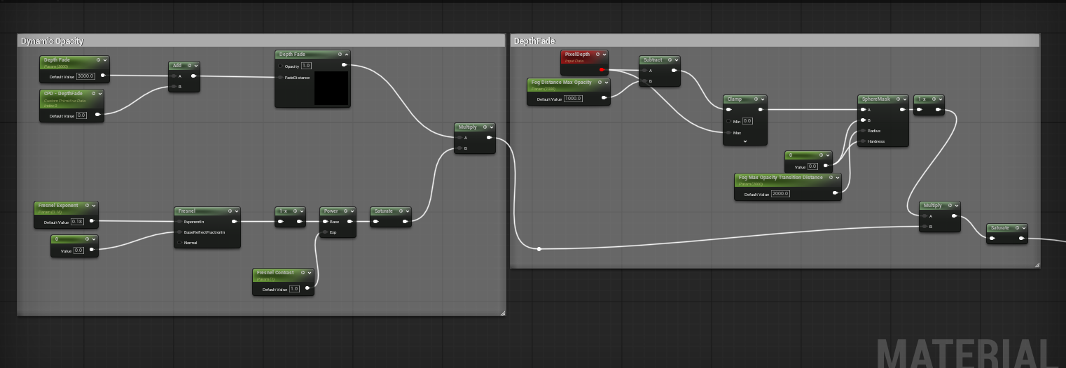
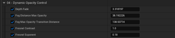
This gives parameters for
depth fadingwhich can be tweaked to create a subtle fade out to afog cardas the camera comes closer to it.Below is an example of some subtle fade parameters:
High Resolution Fog
In high resolution renders Volumetric Fog Pixels can become more visible.
This mostly occurs in light shafts but affects all volumetric fog in a scene.
To reduce the visibility of these
volumetric pixels, add aConsole Variableforr.VolumetricFog.GridPixelSize.The default
Valueis8and should be lowered to reduce the size of theFog Pixelsfor a more desirable visual result:
Additionally, if
Volumetric Fogorlight shaftsremain pixelated or unsmooth, raise ther.VolumetricFog.GridSizeZconsole variable:The default value is 128 and this value should be raised to increase quality:

These settings will have an effect on GPU overhead so should be used sparingly and incrementally increased until no more visual fidelity is found.
Depth Based Post-Process Effects
Post Process Materials that use the Scene Depth buffer can cause visible seams due to each face having a different Screen Space Calculation.
This can be avoided by modifying the the Scene Depth input of the Post Process Material:
Open your
Post Process Materialin theMaterial Editorand check if it is using theSceneDepthbuffer: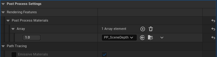
In the Material Graph, delete the
SceneTexture:SceneDepthnode: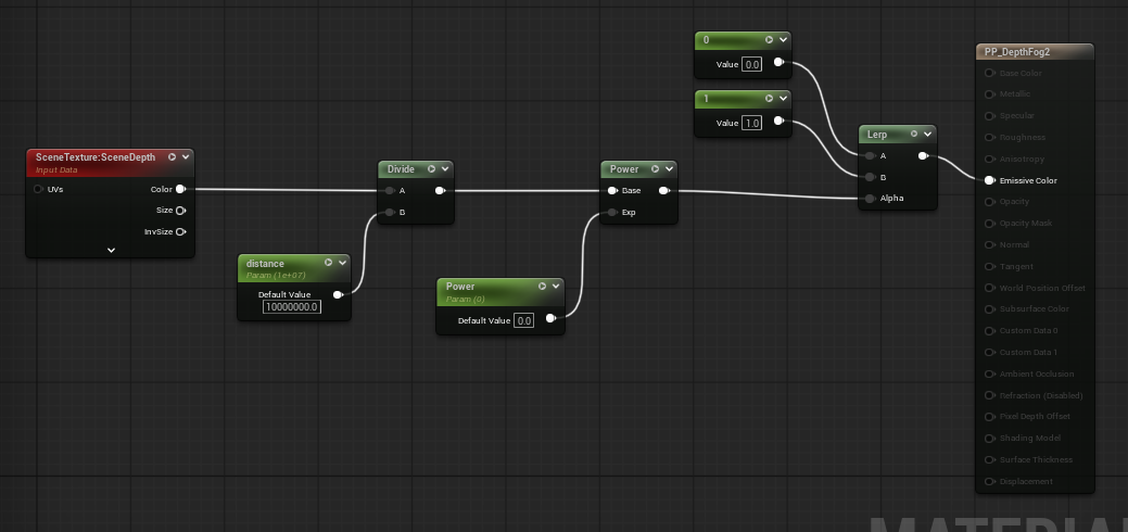
in place of the
SceneTexture: SceneDepthnodeadd thenodesshown in the image below:Add an
Absolute World Positionnode (found by searchingWorld Position) and aCamera PositionNode:Add these two nodes as input
AandBof aSubtract NodeAdd the result to the
Vector 3input of aVector Length NodeAdd this new calculation as the input for the rest of the
materiallogic to create a seamlessDepth Pass-basedmaterial: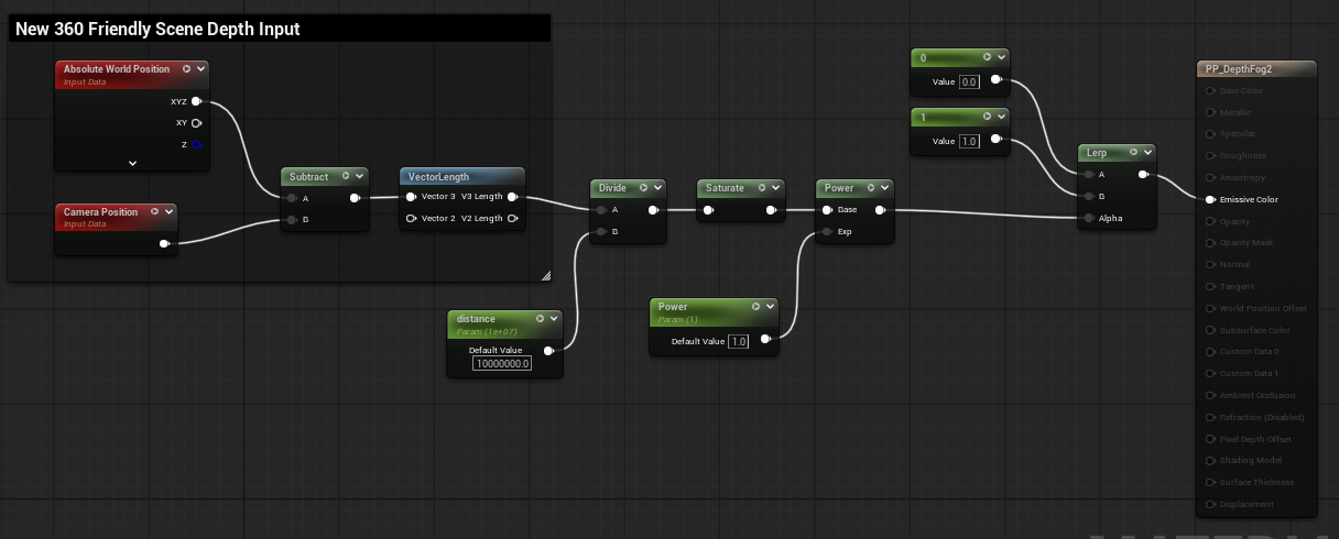
If the
Material’soutput is unsmooth or jittering eachframe, change thePost Process Material>Blendable Locationof theMaterialtoScene Color Before DOF: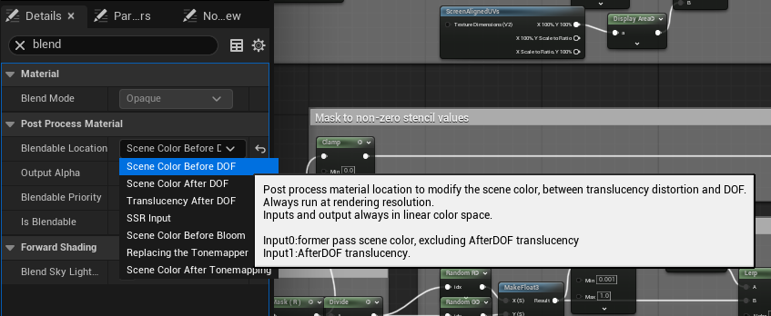
The result is seamless
depth-basedpost process materials: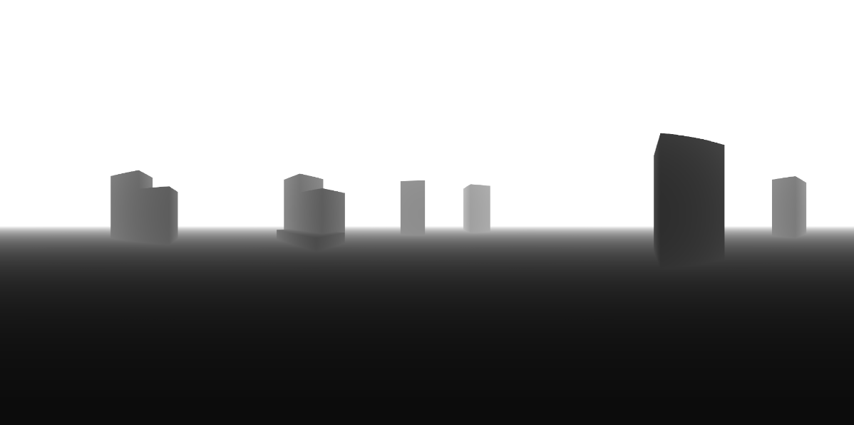
Depth of Field
Depth of Field effects can be achieved through the Post Process Settings of the OWL 360 Camera:
In general, we don’t recommend changing focus during a shot (focus pull) although this can very occasionally be used in Domemaster or VR180 content for dramatic effect.
However, you can set a specific focal point for the duration of a shot which can highlight a specific subject for the viewer such as in the example below:
The three main settings to use are:
Sensor Width:This is measured in mm, raising this value will effectively increase the blur amount.Squeeze Factor:A more subtle way to increase the size of the blurFocal Distance:The distance incmwhere objects are in focus. Combining this withsensor widthandsqueeze factorcan help when dialling in afocus pulleffect.
Dirt Mask
Dirt Masks overlay a 2D image on to the screen, so won't work when enabled in the 360 Camera’s Post Process Settings, since the Dirt Mask will be applied to all cube faces identically, so the image will be repeated.
Instead use the method below:
You can wrap the
Dirt Masktexture around aSphere: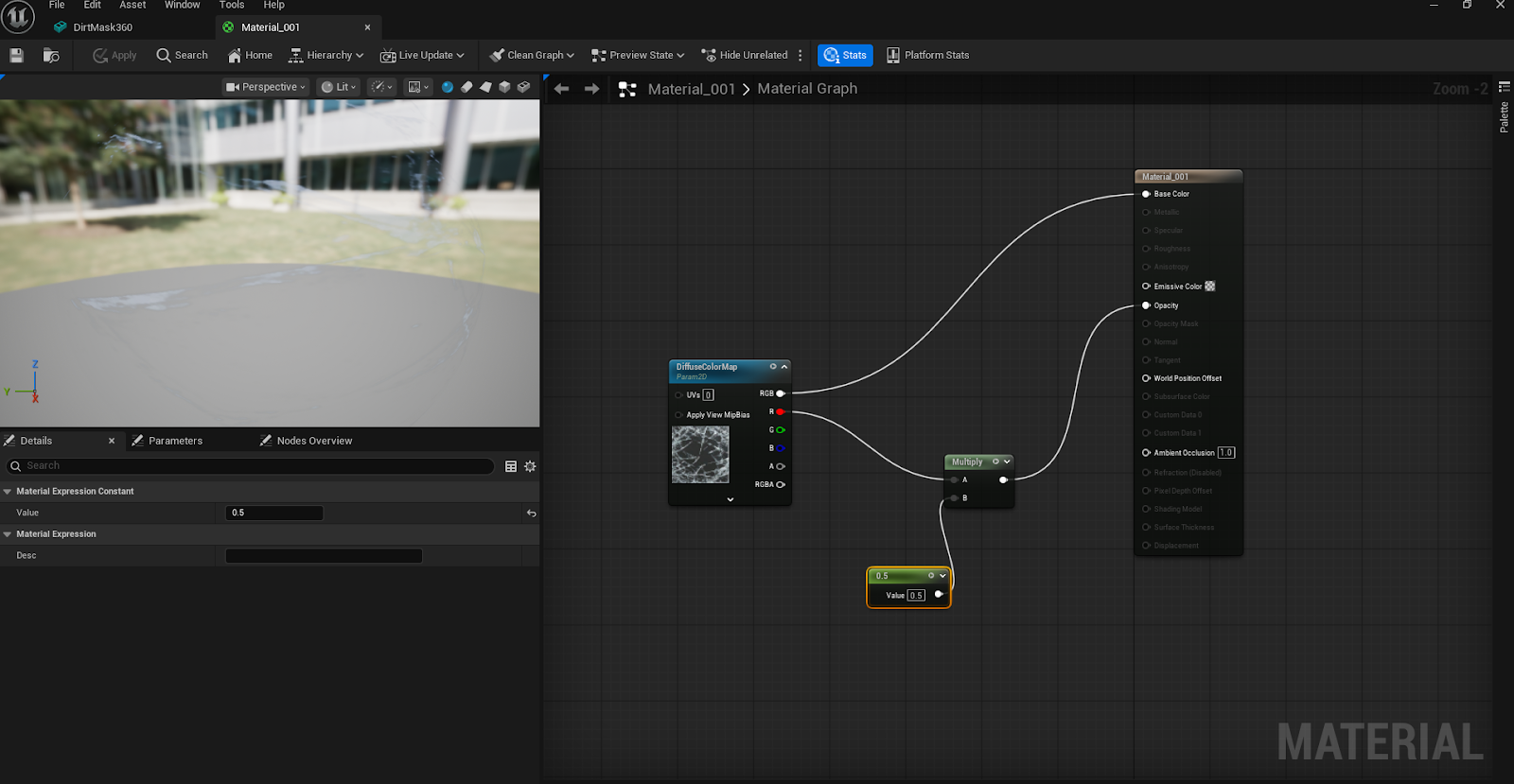
The position the
Spherearound the360 Camera: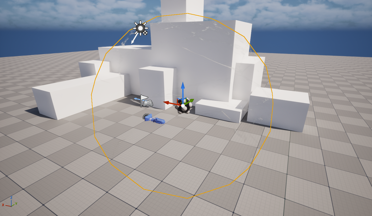
The viewer’s
field of viewwill be significantly more zoomed in, sodirt maskswill need to be more intensely packed together.Full image
Example
field of viewin VR headset (might need moredirt maskdetail).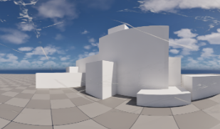
The viewer will also be free to look around the whole map, so dirt masks with a central focal point may not be as effective.
Bloom
Our seamless bloom algorithm is currently only available for our 360 Camera not Movie Render Queue. Until that is complete, please use the tips below.
Bloom can cause seams due to a disparity between the six camera faces arising from screen-space calculation mismatches.
In most cases, adding a
Face Blend Percentageof5can help (increase as you need):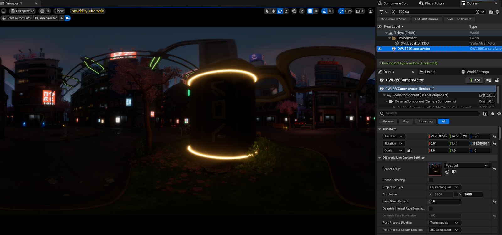
When the camera is moving quickly, seams may still be visible, this can be mitigated by adding temporal Anti Aliasing Samples.
In the case of highly complex bloom, currently we would recommend adding bloom in post production software such as DaVinci Resolve or After Effects.
Water Reflections
Large bodies of water and other large reflective surfaces can cause visible seams.
It’s not always possible to totally fix this, but we can remedy it in most cases with these techniques.
If your seams are caused by moving water, then you may be able to use anti-aliasing to remove them.
First try these steps to see if they will stop seams in the water already in your scene:
In your
Sky Light, setCast Volumetric Shadowto off to stop any seams in the water caused by lighting.In your
Volumetric Cloud ActorMaterialdouble click them.simpleVolumetricCloudand set theWind Vectorto0,0,0,0tu turn off seams caused by moving clouds.
If not, follow these steps:
Open the
Environment Light Mixerand create aSky Light,Atmospheric Light,Sky Atmospheric,Volumetric Cloud, andHeight Fog: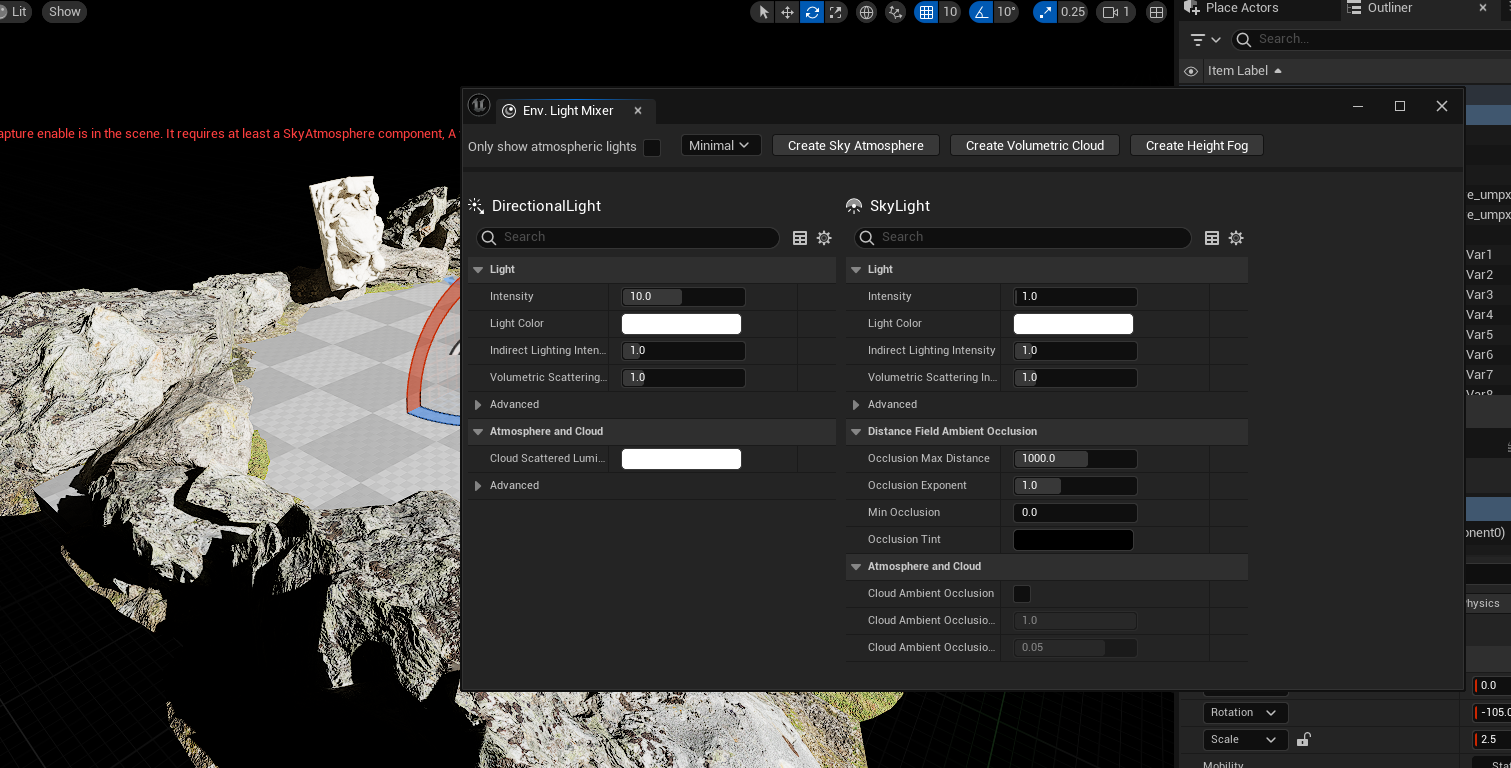
Add a
Water Materialto aGround PlaneorFloor Mesh.For this example we will use the
M_Waterthat comes with theEngine Content: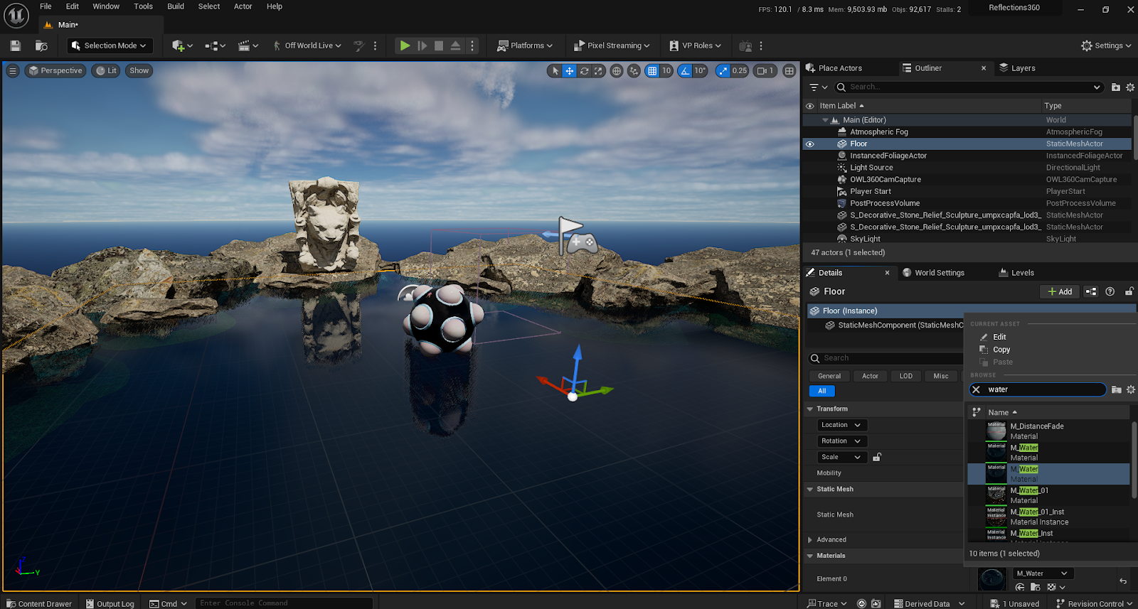
Edit the
Water Materialso that when close to the camera it will have no reflection.This will result in a fade out rather than a harsh line in the reflections:
Make a
New Folderin yourContentfolder and call itWater: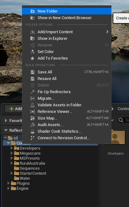
Navigate to the
Water Materialby clicking on it in theOutlinerorViewportthen clicking theBrowse to Assetbutton: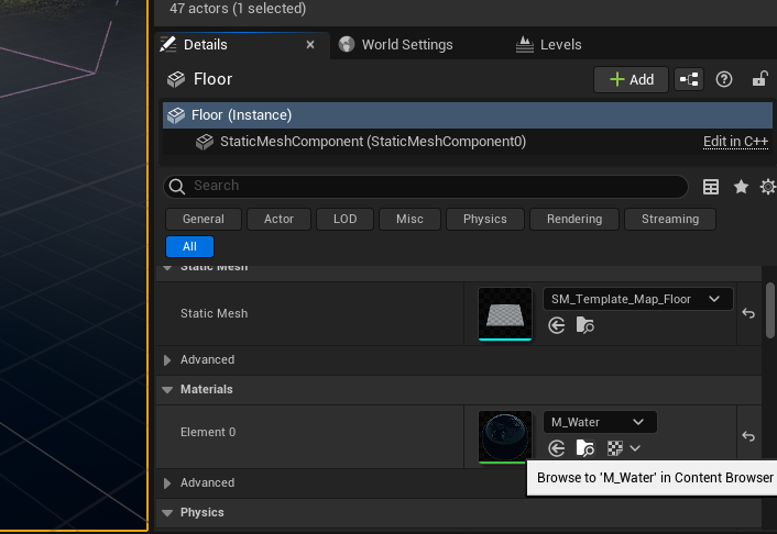
Copy and paste the
Water Materialinto your newly created folder: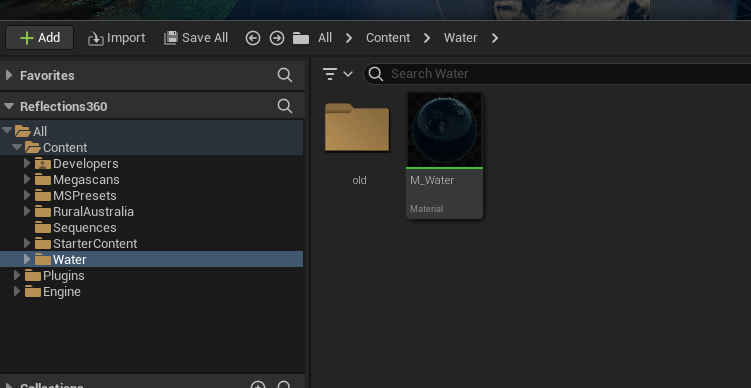
Rename this asset
M_Water1: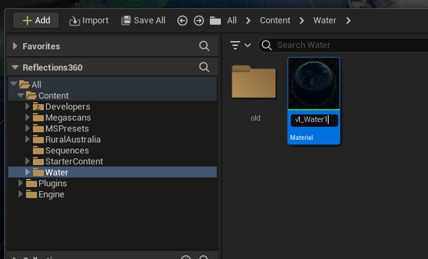
Double click this
Materialto open it. You will see aMaterial Function, we need to copy this as well.Click on the
Material FunctionMFAttr_Water. Then use theBrowse to Assetbutton in theMaterial ExpressionDetailspanel.Once you have this asset located, copy and paste this into your new
Folderand rename thisMFAttr_Water1: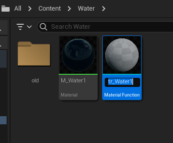
Now go into the
M_Water1 Materialand swap the newMFAttr_Water1 Material Functionin: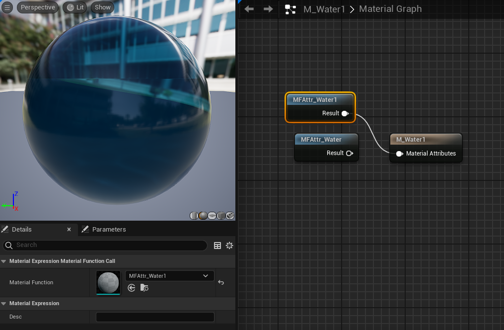
Double click the
Material Function MFAttr_Water1: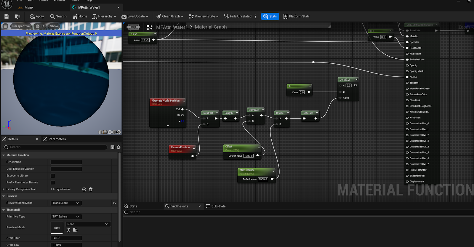
Add the
Nodesin the image below and hook theLerp Bin to theSpecular Output: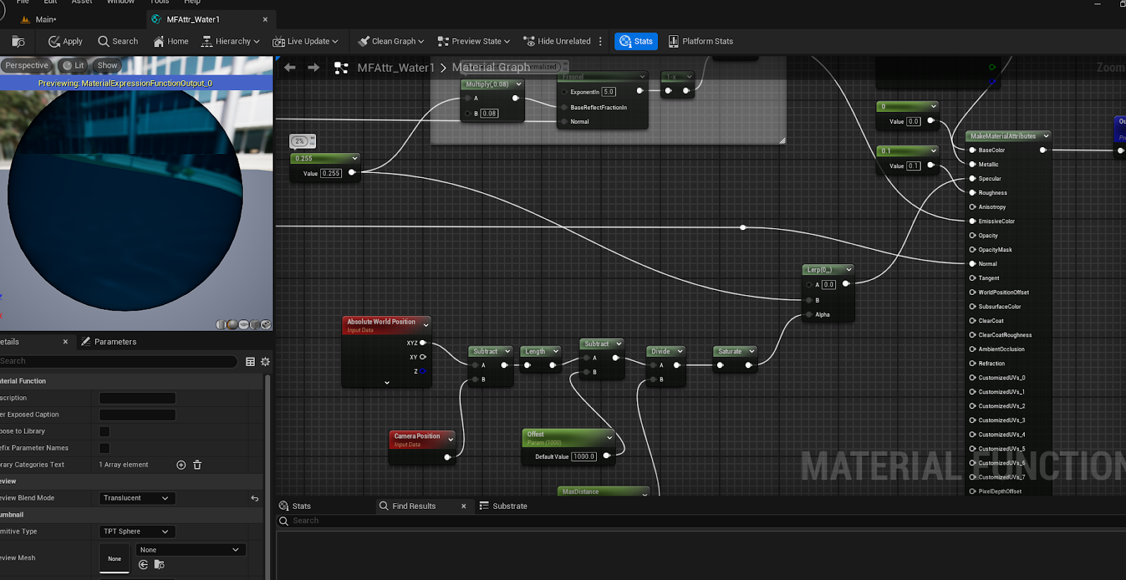
Now you can create a
Material Instanceof your newWater Material: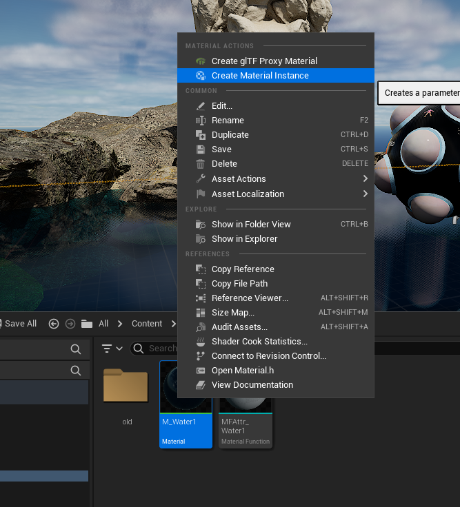
Add it to the
Floor Plane(or wherever you need):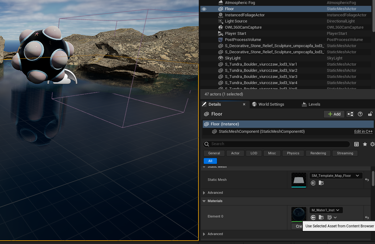
You can change the
MaxDistanceandOffsetso that you get a smooth fade from no specular to full specular reflections: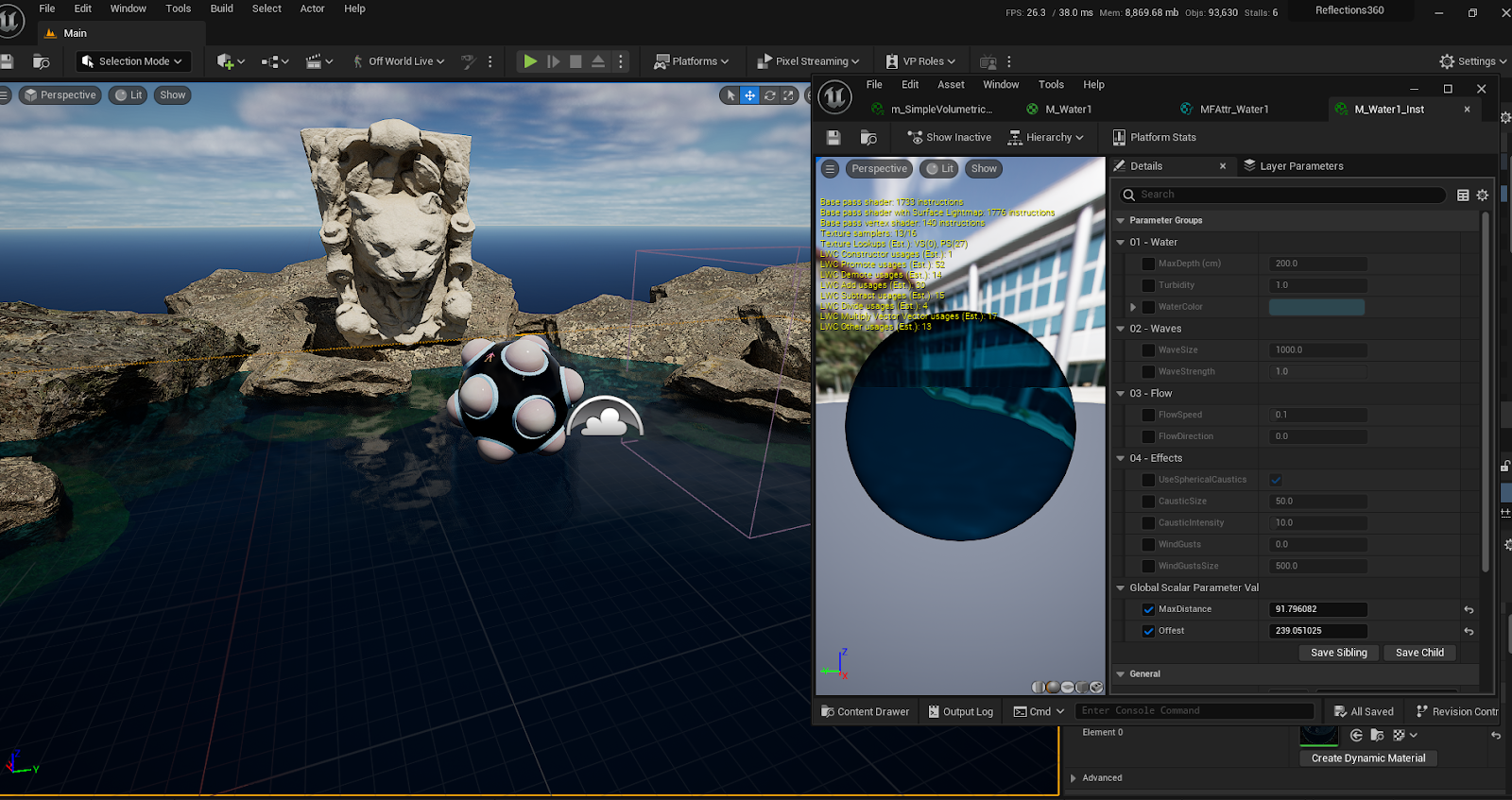
Waves
We can use the same technique but for another
Material Functionwithin the newMFAttr_Water1 Material Functionwe created aboveFind the
MF_Wave_3B_Normals Material Functionin theMFAttr_Water1 Functionand make a copy of it.Connect the new
MF_Wave_3B_Normals2to the left and right nodes (replacing the old one):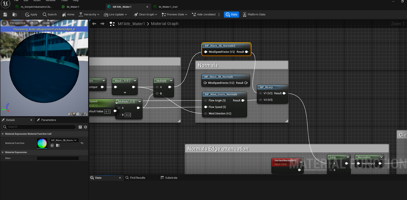
Double click on
MF_Wave_3B_Normals2to open it, then add the below highlighted nodes and connect them into the 'A' Input of aLerp, with the original output going to the 'B' Input of theLerp.Copy the
Wave Strength Parameterand rename it toWave Strength0, then copy theNimandMF_normal Strengthnodes to result in the image below: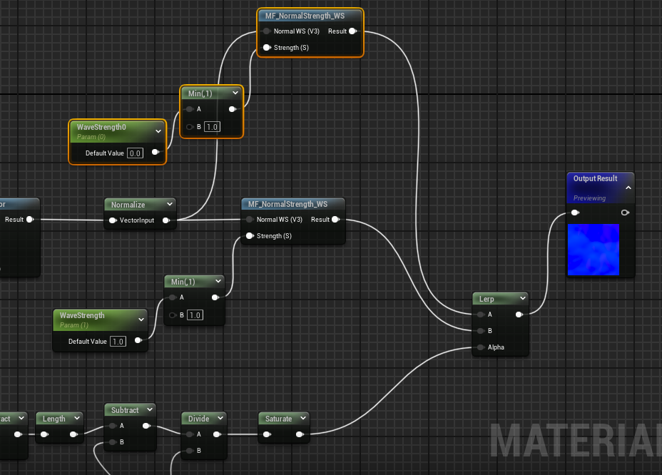
You will now be able to control the wave
Max DistanceandWave Offsetto make the appearance of the waves dependant on their distance from the camera: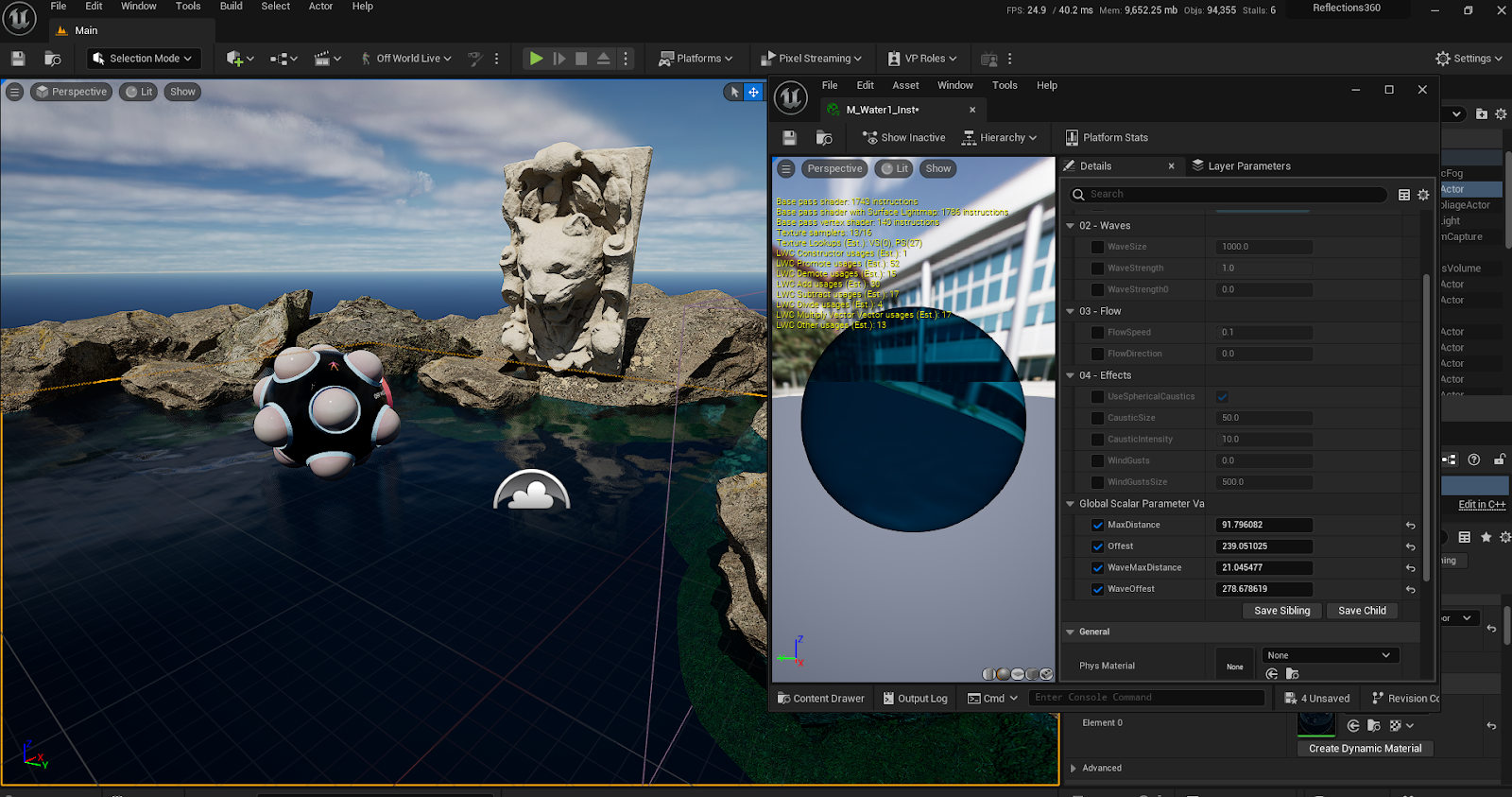
Motion Blur
Increasing your
Sample countcan fix jagged edge geometry, Motion Blur and other distracting or unrealistic artefacts in renders.Raising
Anti aliasing Temporal Sample CountinMovie Render Queue Settingscan help to average out lighting calculations over seam overlaps, and smooth out distracting artefacts.A
Temporal Sample Countof as low as4alongsideDLAAwithMotion Blur Separableticked can give a smooth moving image in most scenarios.Ensure that you preview any
Anti Aliasingchanges at a lower preview resolution before submitting a large render job to check that your changes are actually fixing your issues (so you don’t increase your final render time for nothing).
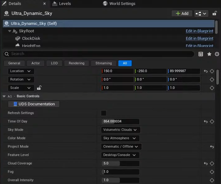
Ultra Dynamic Sky
When using
tilinginhigh resolution rendering,Ultra Dynamic Sky’srandom elements such as cloud movement can cause visible seams between faces due to them having true randomness which is deployed differently for each Movie Render Queue job.Fortunately
Ultra Dynamic Skyhas aCinematic/OfflineProject Mode.Not only is this useful for art directing sky to be exactly as intended, but it also makes all randomness deterministic, based off of a seed value, removing any cloud based seams:
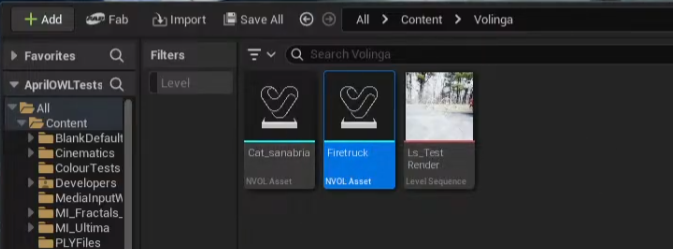
Gaussian Splats
There are multiple plugins for Unreal Engine which allow for Import of the standard Gaussian Splat PLY file.
The paid plugin Volinga allows for 360 rendering of Gaussian Splats through Movie Render Queue.
With the Volinga plugin enabled, drag a PLY file in to the content browser to convert it in to their Radiance Field NVOL actor:
This actor can now be dragged in to the Viewport and rendered in 360 through Movie Render Queue.